C H A P 5, SEC X X X I II
A S S E M B L Y
P A R 2 2 7 , S T E P S 2 7 - 3 0
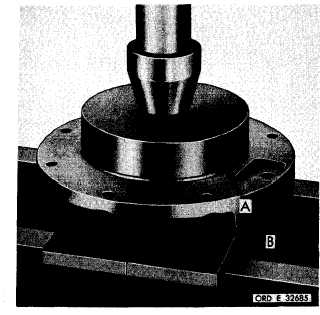
Figure 266 (Step 27)
P r e s s l e f t - o u t p u t c l u t c h s u p p o r t b e a r i n g ( A )
into support (B).
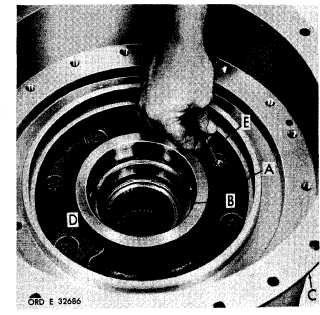
Figure 267 (Step 28)
Install support (A) and bearing (B) into trans-
mission housing (C). Secure sleeve with one
3 / 8 - 1 6 x 2 ( D ) a n d s e v e n 3 / 8 - 1 6 x 1 - 1 / 4 ( E)
self-locking bolts. Using a 9/16-inch wrench,
torque bolts to 36-43 pound-feet.
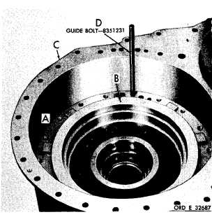
Figure 268 (Step 29)
I n s t a l l s t e e r c l u t c h p i s t o n a s s e m b l y ( A ) , l o -
cating oil hole (B) in the assembly in relation
t o t r a n s m i s s i o n h o u s i n g ( C ) , a s s h o w n . I n-
stall guide bolt (D).
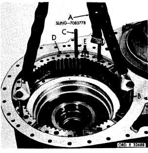
Figure 269 (Step 30)
U s i n g s l i n g ( A ) , t h r e e 7 / 1 6 - 1 4 x 5 b o l t s ( B)
and guide bolt (C), install steer clutch anchor
( D ) . I n d e x h o l e s ( E ) o f t h e a n c h o r w i t h t he
holes in the transmission housing.
1 7 0
|
|