C H A P 5, SEC X X X I II
A S S E M B LY
P A R 2 2 7 , S T E P S 6 7 - 7 0
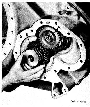
Figure 306 (Step 67)
Install snap ring (A). Install output oil pump
drive gear (B), flat side out.
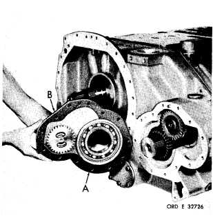
Figure 307 (Step 68)
Install gasket (A) on left-output support as-
s e m b l y ( B ) . I n s t a l l s u p p o r t a s s e m b l y.
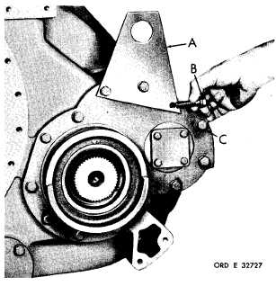
Figure 308 (Step 69)
I n s t a l l l i f t i n g b r a c k e t ( A ) , t h r e e 7 / 1 6 - 1 4 x
1 - 3 / 4 ( B ) a n d t e n 7 / 1 6 - 1 4 x 1 - 1 / 2 b o l t s ( C)
with lock washers. Using a 5/8-inch wrench,
torque bolts to 42-50 pound-feet.
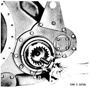
Figure 309 (Step 70)
I n s t a l l l e f t - o u t p u t c o u p l i n g ( A ) . I n s t a l l l o ck
plate (B) and 3/4-16 x 2-3/4 bolt (C), finger
tight.
1 8 0
|
|