*C2
C H A P 5, SEC X X X I II
A S S E M B L Y
P A R 228, STEPS 1 9 - 2 2
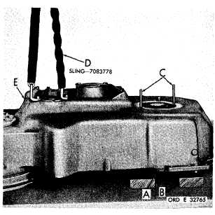
Figure 346 (Step 19)
Position torque converter assembly (A) on the
assembly table, leveling it on wooden blocks
( B ) . I n s t a l l t w o 3 / 8 - 2 4 h e a d l e s s g u i d e b o l t s
( C ) i n a s s e m b l y ( A ) . U s i n g s l i n g ( D ) , l o w er
input transfer gear housing assembly (E) onto
c o n v e r t e r a s s e m b l y ( A ) . A f t e r i n s t a l l a t i o n,
level housing assembly (E) with wooden blocks.
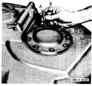
Figure 347 (Step 20)
R e m o v e h e a d l e s s g u i d e b o l t s . I n s t a l l t o r q ue
converter bearing cover (A) and gasket (B).
1 9 0
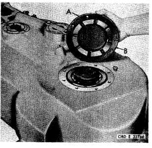
Figure 348 (Step 21)
Install eight 3/8-24 x 2-1/4 bolts (A) and lock
washers (B) to retain converter bearing cover
( C ) . U s i n g a 9 / 1 6 - i n c h w r e n c h , t o r q u e b o l ts
to 33-40 pound-feet.
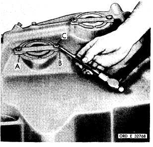
Figure 349 (Step 22)
Install transfer idler cluster gear spindle lock
strap (A), lock strip (B) and two 3/8-16 x 1
b o l t s ( C ) . U s i n g a 9 / 1 6 - i n c h w r e n c h , t o r q ue
b o l t s t o 2 6 - 3 2 p o u n d - f e e t . B e n d c o r n e r s o f
strip (B) against bolt heads.
|
|