Figure 21
C H A P 2, SEC V
T O R Q U E P A T H S
P A R 4 5
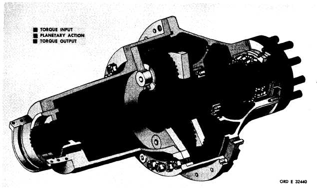
Figure 21. Output drive torque path
45.
TORQUE
PATH
-
OUTPUT
DRIVES
( f i g . 2 1)
a . F i g u r e 2 1 i s a c u t a w a y v i e w o f t h e
left-output drive (mounts at right side of power
train). The construction of the right assembly
i s i d e n t i c a l e x c e p t f o r l e n g t h ; o p e r a t i o n i s
i d e n t i c a l.
b . T o r q u e i s t r a n s m i t t e d f r o m t h e m a in
transmission section output to the output drive
assembly by the output drive sun gear shaft.
The integral sun gear imparts torque to the
planetary pinions which are mounted in a sta-
tionary carrier. In turn, the pinions transmit
torque to the ring gear. The ring gear, splined
to the output shaft, transmits torque to the
output shaft.
c . Arrows indicating the direction of ro-
t a t i o n i l l u s t r a t e c o n d i t i o n s w h e n t h e p o w er
train is operating in a forward gear. In a re-
verse gear, all rotations would reverse. Note
that the output drive output rotation is opposite
that of the output drive input because the re-
a c t i o n m e m b e r ( s t a t i o n a r y m e m b e r ) i s t he
p l a n e t a r y c a r r i e r.
4
8
|
|