TM 9-2520-272-34&P
Section III. TRANSMISSION ASSEMBLY FROM MAJOR ASSEMBLIES
Paragraph
Title
Page
4-12
Install Bevel Gear Assembly
4-44
4-13
Install Input Housing Assembly
4-46
4-14
Install Converter Element Components
4-49
4-15
Install Left End Cover Assembly
4-56
4-15.1
Install Oil Fill Tube Assembly
4-63.1
4-16
Install Right End Cover Assembly
4-64
4-17
Remove Transmission from Maintenance Stand
4-73
4-18
Install Transmission Top Components
4-80
4-12. INSTALL BEVEL GEAR ASSEMBLY (SHEET 1 OF 2)
Task
Title
Page
1
Install Bevel Gear Assembly
4-44
TASK 1. INSTALL BEVEL GEAR ASSEMBLY
COMMON TOOLS:
Extension, socket wrench, 1/2 inch square drive, 10
inch
Handle, socket wrench, 1/2 inch square drive
Hoist, 300-pound minimum capacity
Socket, socket wrench, 1/2 inch square drive, 9/16
inch
SPECIAL TOOLS:
Lifting Sling, three-leg (19207) 12268036
SUPPLIES:
Bolt, hex head, 3/8-16 x 1-1/4 inch (3 required)
Washer, flat, 3/8 inch (3 required)
NOTE
Transmission on maintenance stand,
input side turned up.
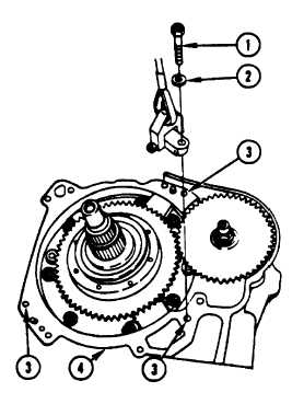
1.
Using socket, attach three 3/8-16 x 1-1/4 inch
bolts (1) and washers (2) through sling lugs and
into three bolt holes (3) in housing (4).
Go to Sheet 2
4-44 Change 2
Para. 4-12, Task 1
|
|