TM 9-2520-272-34&P
4-19.
DISASSEMBLE RIGHT END COVER ASSEMBLY
(SHEET 12 OF 16)
16
17
18
19
20
21
22
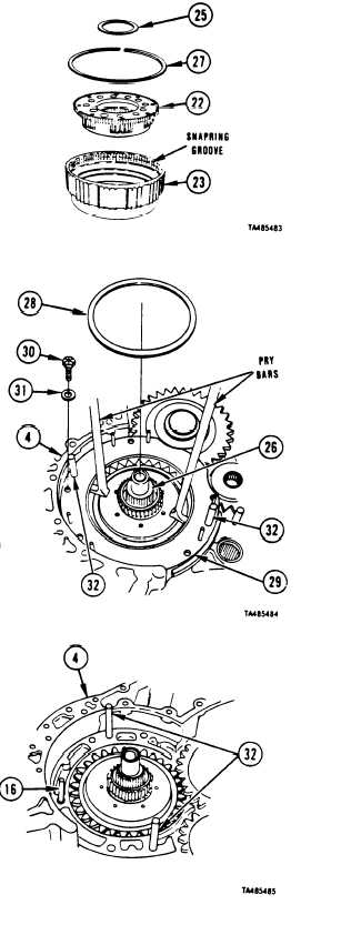
Turn output carrier (22) and drum (23) upside down.
NOTE
Thrust washer (25) usually comes off end
cover (4) inside output carrier (22), but it
may remain on RH steer driven gear (26).
Remove thrust washer (25) from output carrier (22).
Using screwdriver, remove snapring (27) from drum
(23).
Remove carrier (22) from drum (23).
Remove brake coolant seal (28) from brake clutch
backing plate (29).
Using 9/16 inch socket, remove four bolts (30) and
washers (31) from brake clutch backing plate (29).
NOTE
Plate (29) may bind on two pins (28) during
removal. It may be necessary to tap plate
near pin, using plastic faced hammer, to
help release plate.
Using two pry bars under
plate (29), remove plate.
NOTE
insid e edge of clutch backing
Six spring guide pins (16) may come with
plate (29), or pins may remain in end cover
(4).
23 Remove six spring guide pins (16) from backing plate
(29) or from right end cover (4).
FOLLOW-ON PROCEDURE:
• Install right brake assembly. Refer to paragraph
4-21.
• Install brake apply cam and brake adjust linkage.
Refer to paragraph 4-21.
End of Task 6
Go to Sheet 13
Para. 4-19, Task 6
4-107
|
|