TM 9-2520-272-34&P
4-20.
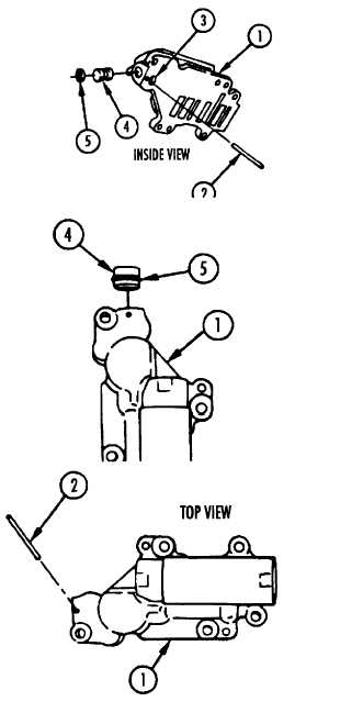
REPAIR RIGHT END COVER COMPONENTS TM 9-2520-272-34&P
(SHEET 2 OF 14)
3 Turn valve body (1) over, inside up.
4 Insert tip of screwdriver in hole (3) and pry plug
(4) from body.
5 Remove packing (5) from plug (4).
Assemble Brake Apply Regulator Valve Body (X200-4
Only)
6
Install new packing (5) on plug (4).
7
Apply petrolatum to packing (5)
8
Place body (1) on table, plug port end up.
9
Place plug (4) over bore in body (1), chamfered
end of plug in first.
10 Install plug (4) and packing (5) against seat in
body (1). Tap plug lightly with hammer if
necessary.
11 Place valve body (1) on table, outside up.
12 Using hammer and punch, install new pin (2) in
body (1). Seat pin flush to 0.020 inch (0.508
mm) below flat inside surface of body.
FOLLOW-ON PROCEDURE:
Install brake apply regulator valve components.
Refer to paragraph 4-21.
End of Task 1
TASK 2. REPAIR INNER BRAKE ADJUSTING LINK
ASSEMBLY
NOTE
Do not remove inner brake adjusting link
pin unless repair is necessary.
COMMON TOOLS:
Gage, vernier caliper
Hammer, hand, ball peen
Punch, center
Vise, soft jaw
REPAIR PARTS:
Pin, spring (24617) 455675
Go to Sheet 3
Para 4-20, Task 2
Change 2 4-113
|
|