TM 9-2520-272-34&P
4-20.
REPAIR RIGHT END COVER COMPONENTS
(SHEET 3 OF 14)
SUPPLIES:
Rag, wiping (Item 15, Appendix C)
PRELIMINARY PROCEDURE: Inner brake adjusting
4-19.
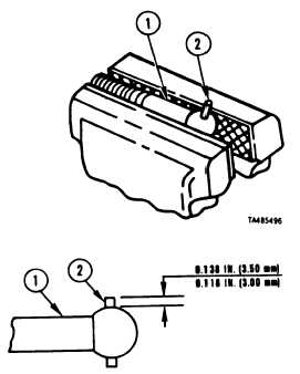
Remove Pin
1 Place inner brake adjusting 1 ink (1) in vise.
2 Using hammer and punch, drive pin (2) from link (1).
Install Pin
3 Using hammer and punch install new pin (2) to a
height of 0.118-0.138 inch (3.00-3.50 mm) above
surface of link (1).
4 Remove link (1) from vise.
FOLLOW-ON PROCEDURE: Install inner brake
adjusting link. Refer to paragraph 4-21.
End of Task 2
link is remov ed. Refer to paragraph
TASK. 3. REPAIR LEFT BRAKE APPLY SHAFT ASSEMBLY
COMMON TOOLS:
Gage, vernier caliper
Hammer, hand, ball peen
Punch drive pin, 1/16 inch point
REPAIR PARTS:
Pin, spring (24617) 9421003
PRELIMINARY PROCEDURE: Remove left brake
apply shaft. Refer to paragraph 4-19.
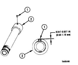
1 U s i ng
brake
punch and hammer, remove pin (1) from left
apply shaft (2).
2 U s i ng
(2) to
below outside surface of shaft.
punch and hammer, install new pin (1) in shaft
a depth of 0.027-0.047 inch (0.68-1.19 mm)
Go to Sheet 4
4-114
Para. 4-20, Task 3
|
|