TM 9-2520-272-34&P
4-27.
ASSEMBLE BEVEL GEAR ASSEMBLY
(SHEET 3 OF 5)
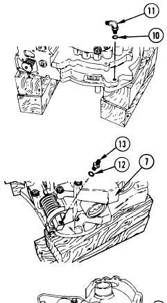
10 Install new packing (10) onto elbow (11). Using
combination wrench, install elbow (11) and packing
(10) into bevel gear housing.
11
12
13
14
15
16
Install new packing (12) onto connector (13). Using
9/16 inch socket, extension, and adapter, install
connector (13) and packing (12) into pump assembly (7).
Using torque wrench, tighten connector (13) to 5-7
lb-ft (7-9 N•m).
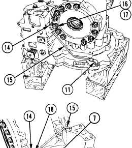
Install two clamps (14) onto reverse signal tube (15).
Using 9/16 inch socket, remove bolt (16) and washer
(17) (if present) from bevel gear carrier.
Using 1/2 inch socket and extension, remove bolt (18)
(if present) from input and scavenge pump assembly (7).
Using combination wrench, install reverse signal tube
(15) onto elbow (11) and connector (13). After ferrule
17
18
19
20
21
is seated, torque the two nuts to 10-12 Ib-ft (13-16
N•m).
Using 9/16 inch socket and extension, install washer
(17) and bolt (16) that retain tube (15) to bevel gear
assembly.
Using torque wrench, tighten bolt (16) to 36-43 lb-ft
(49-58 N•m).
Using 1/2 inch socket and extension, install bolt (18)
that retains tube (15) to pump assembly (7).
Using torque wrench, tighten bolt (18) to 17-20 lb-ft
(23-27 N•m).
Using 9/16 inch crowfoot, extension, adapter and
torque wrench, tiqhten nut that retains elbow (11) to
5-7 Ib-ft (18-22 N•m).
Go to Sheet 4
PARA. 4-27, Task 1 Change 1 4-169
|
|