TM 9-2815-202-34
(3) lnsert drive shaft (11)through blower drive gear(15). lf binding occurs, refer to blower
alinement procedure in para 4-18.
(4) Install snap ring (12) in blower drive hub (18). Remove 10-32 x 1- inch bolt (10 ) from shaft
(11).
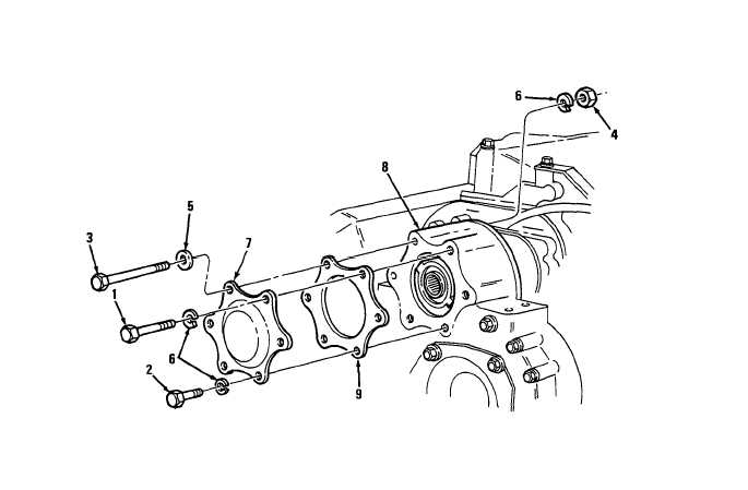
(5) Install blower drive cover (7) and gasket (9) on flywheel housing (8) and secure with two
bolts (1) and two Iockwashers (6).
(6) Install bolt (1), two bolts (2), bolt (3), two Iockwashers (6), flat washer (5), and nut (4) in
remaining holes.
(7) Torque bolt (3) and nut (4) to 35-39 Ib-ft (47-53 N-m). Torque five remaining bolts to
30-35 Ib-ft (41-47 N-m).
END OF TASK
FOLLOW-ON MAINTENANCE
Para Description
4-2
Turbocharger installed (7083-7395)
6-3
Turbocharger installed (7083-7398)
C h a n g e 1 4-55
|
|