TM 9-2815-202-34
4-27. CYLINDER HEAD ASSEMBLY REMOVAL/INSTALLATION
This task covers:
a. Removal
b. Installation
INITIAL SETUP
MODELS
n All
TOOLS AND SPECIAL TOOLS
General mechanics tool kit (App B
Cylinder head lifting fixture (App B
Guide studs (App B, Item 88)
Torque wrench (App B, Item 101)
Item 96)
Item 19)
MANDATORY REPLACEMENT PARTS
2
Seal rings (App F, Item 134)
8
Compression gaskets (App F, Item 83)
2
Seal rings (App F, Item 136)
Seal rings (App F, Item 137)
12
Seal rings (App F, Item 138)
EXPENDABLE/DURABLE SUPPLIES
International compound no. 2 (App C, Item 24)
EQUIPMENT CONDITION
Para Description
4-2
Turbocharger oil line clips removed
(7083-7395)
4-3
Exhaust manifolds removed (7083-7395)
EQUIPMENT CONDITION (Cent)
Para
4-6
4-8
4-10
4-11
4-15
4-17
4-18
4-26
5-3
5-4
5-6
5.1-4
5.1-6
5.1-8
5.1-11
6-4
6-11
Description
Fuel lines removed (7083-7395 and
7083-7398)
Thermostat housings removed (7083-7395
and 7083-7398)
Air box heater removed (7083-7395 and
7083-7396)
Rocker arm covers removed
Block mounted breather disconnected
(Except 7083-7398 and 7083-7399)
Governor cover and throttle-control rods
Fuel rod hoses detached
Injector control tubes removed
Exhaust manifolds removed (7083-7391
and 7083-7396)
Fuel lines removed (7083-7396 and
7083-7399)
Water manifolds removed (7083-7396
and 7083-7399)
Fuel lines removed (7083-7391)
Water manifolds removed (7083-7391)
Glow plug harness removed (7083-7391)
Air inlet by-pass valve hoses detached
(7083-7391)
Exhaust manifolds removed (7083-7398)
Air box heater removed (7083-7398
a n d 7 0 8 3 - 7 3 9 9 )
Exhaust manifolds removed (7083-7399)
7 - 4
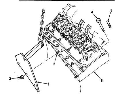
a. Removal
(1)
(2)
(3)
(4)
Attach lifting bracket (1) to center three
exhaust manifold studs (2) located at
outboard side of cylinder head. Secure in
place with three 7/1 6-20-inch nuts (3).
Attach a chain to lifting bracket (1) and take
up slack in chain.
Remove two cylinder head bolts (4) at
outboard corners of cylinder head and
install guide studs (5). Remove remaining
eight cylinder head bolts (4).
Lift cylinder head assembly (6) from
cylinder block.
4 - 9 8
Change 1
|
|