TM9-2815-202-34
(27) Adjust bridges as follows:
CAUTION
Do not loosen or tighten locknut with
bridge installed in cylinder head.
Bent bridge guide or rear valve stem
may result.
(a)
(b)
(c)
(d)
(e)
(f)
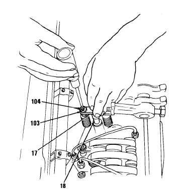
Place valve bridge (17) in a vise
or bridge holding fixture and
loosen locknut (103)on bridge
adjusting screw (104).
Install valve bridge (17) on valve
bridge guide (18).
While firmly pressing straight
down on pallet surface of valve
bridge (17), turn adjusting screw
(104) clockwise until it just
touches valve stem. Then turn
screw an additional 1/8 to 1/4 turn
and tighten locknut (103) finger
tight.
Remove valve bridge (17) and
place in a vise or holding fixture.
Hold adjustment screw (104) from
turning with screwdriver and
torque locknut (103) on
adjustment screw to 20-25 Ib-ft
(27-34 N-m).
Lubricate valve bridge (17) and
valve bridge guide (18) with
engine oil and install bridge in
original position.
Place 0.0015 inch feeler gage
under each end of valve bridge
(17). When pressing down on
pallet surface of valve bridge,
both gages must be tight. If both
feeler gages are not tight,
readjust screw as outlined in
steps (a) thru (e).
4-211
|
|