|
|
|
|

|
TM 9-2815-202-34
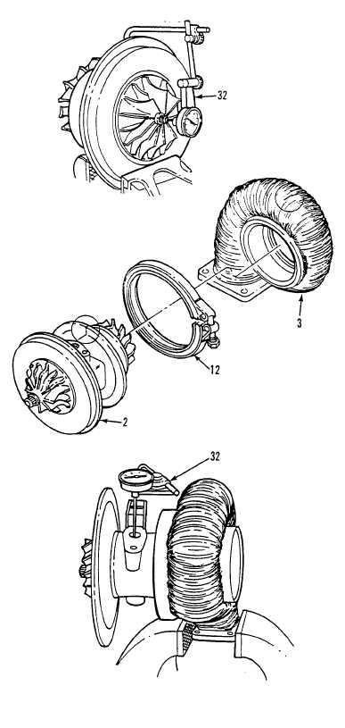
(19) Check bearing axial end play as follows:
(a) Clamp center housing assembly in
soft-jawed vise.
(b) Fasten magnetic base dial indicator
(20)
(21)
(22)
(32) to center housing with indicator
tip resting on end of rotating shaft
on compressor side.
(c) Move shaft axially back and forth by
hand. Total indicator reading should
be between 0.003 and 0.010 inch.
Repair or replace shaft assembly if
readings do not fall within limits.
Install turbine housing (3) on center
housing (2) and align match marks.
Install V-band coupling (12) on turbine
housing (3) and center housing (2) so
T-bolt end does not interfere with
turbine housing. Apply antiseize
compound to threads on T-bolt and
tighten nut to 160 lb-in (18 N-m).
Loosen to 50 lb-in (5.6 N-m) and
retorque to 152-168 lb-in (17.2-19.0
N-m).
Check shaft radial movement as
follows:
(a)
(b)
Position magnetic base dial indicator
(32) on flat surface of turbine
housing inlet flange.
Insert dial indicator tip extension rod
into oil drain hole with rod touching
shaft and perpendicular.
NOTE
Insure adaptor rod does not
contact sides of center housing or
readings are invalid.
(c) Grasp ends of rotating assembly
and apply equal pressure at each
end, moving rotating shaft toward
and away from dial indicator.
Crosswise movement must be
between 0.003 and 0.007 inch.
C h a n g e 15-101
|
|
|
|
|
Privacy Statement -
Copyright Information. -
Contact Us