TM9-2815-202-34
(3) Using feeler gage, measure ring side
clearance. Refer to Table 6-2 for ring
side clearance specifications.
g. Assembly
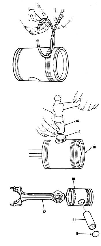
(1) Connecting Rod Assembly to Piston
(a) Apply clean engine oil to piston
pin and piston pin bushings.
Do not drive piston pin retainer in
too far. Retainer may move piston
bushing inward and result in reduce
piston pin end clearance.
(b) Insert one piston pin retainer (9)
in position. Then place crowned
end of installer (14) against
retainer and strike installer just
hard enough to deflect retainer
and seat it evenly in piston (10).
NOTE
Since loading on the piston pin is
downward, it must have free
movement to secure perfect
alinement and uniform wear.
Therefore, the piston pin has a full
floating fit in connecting rod and
piston bushings. Large clearances
of 0.010 inch maximum are allowed.
(c)
(d)
(e)
Place upper end of connecting
rod assembly (12) between
piston pin bosses and in line with
piston pin holes. Then slide
piston pin (11) in place.
Install second piston pin retainer
(9) as directed in step (b).
Check for piston pin end
clearance by cocking connecting
rod and shifting pin in bushings.
6-37
|
|