TM9-2815-202-34
6-38. TURBOCHARGER REPAIR (Cont)
(11)
(12)
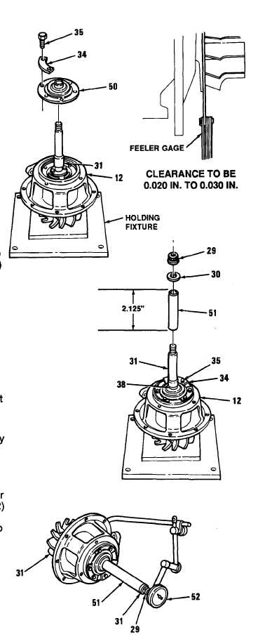
Slide thrust plate assembly (50) over
rotor assembly (31 ). Aline holes in
thrust plate assembly with holes in
center housing assembly (12).
Install three locking plates (34) and
(13)
(14)
(15)
(16)
(17)
(18)
six bolts (35) securing thrust plate
assembly (50) to center housing
assembly (12). Torque bolts to
80-100 lb-in (9-11.4 N-m).
NOTE
Back plate shim comes in a 0.010
inch thickness.
Push rotor assembly (31) toward
compressor end of turbocharger.
Using feeler gage, measure
clearance between rotor assembly
and back plate (43). Repeat steps (2)
thru (12) to add or remove shims (44)
until clearance is between 0.020 to
0.030 inch.
Bend up tangs on locking plates (34)
against heads of bolts (35).
Install fabricated sleeve (51) over
shaft of rotor assembly (31) and
against face of thrust collar (38).
Sleeve length is 2.125 inches.
Secure rotor assembly and center
housing assemblv (12) in place with
washer (30) and nut (29). Tighten nut
securely.
Using dial indicator (52), measure
axial play of rotor assembly (31). Play
should be 0.005 to 0.010 inch.
Remove nut (29), washer (30), and
sleeve (51).
Install diffuser shims (33) and diffuser
(27) on center housing assembly (12)
and secure with four nuts (25) and
four Iockwashers (26). Torque nuts to
150-200 lb-in (17-22 N-m).
6-50
|
|