TM 9-2815 -202-34
r.
s.
t
u.
v.
w.
x.
Repeat check on 1 L and 1 R injector rack
control levers as outlined in step i. If 1 L is
loose, then 1R should be readjusted. If 1 R
is loose, than 1 R should be adjusted.
NOTE
Once 1 L and 1 R injector rack control
levers are adjusted, do not alter
their settings. Make further
adjustments only on remaining
control racks.
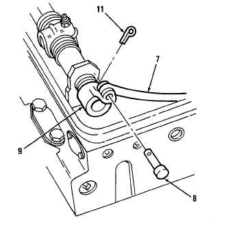
Hold governor speed control lever (12) in
FULL FUEL position. Check clevis pin (8)
for drag on right and left control tube lever.
Both pins should be free.
Move governor speed control lever (12) to
maximum speed position and hold in
position with light finger pressure.
Adjust 2L, 3L, and 4L, as outlined in steps e
thru k. Check adjustment on each injector
control rack (13). Do not readjust 1 L.
Move speed control lever (12) to maximum
speed position and hold in position with
light finger pressure.
Adjust 2R, 3R, and 4R as outlined in steps e
thru k. Do not readjust 1 R.
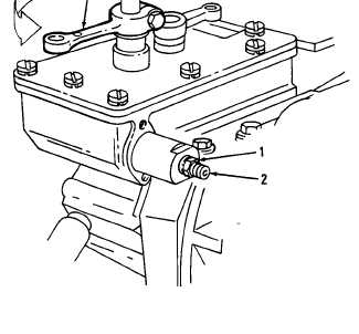
Turn idle speed adjusting screw (2) in until
it projects 0.20 inch from-locknut (1) to
permit starting of engine. Tighten locknut.
END OF TASK
FOLLOW-ON MAINTENANCE
Para
4-11
8-8
8 -9
8-10
8-11
8-12
8-13
Description
Install rocker arm covers.
Adjust throttle delay (7083-7395 and
7083-7396).
Adjust starting aid screw (7083-7391,
7083-7395, and 7083-7396).
Adjust idle speed.
Install governor spring housing (Dual
range limiting speed governor)
(7083-7395 and 7083-7398).
Install governor spring housing (Limiting
speed governor) (7083-7391, 7083-7396,
and 7083-7399).
Adjust buffer screw.
FULL FUEL
Change 1
8-19
|
|