f.
l
l
9.
h.
i.
j.
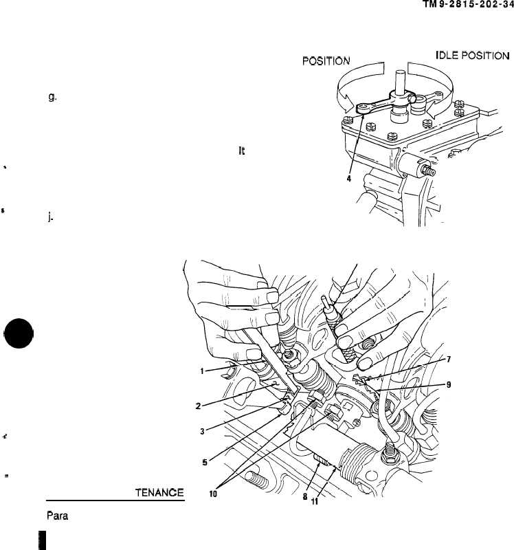
Check the throttle delay setting. If 0.072
inch end of pin gage enters fill hole (7),
tighten upper U-bolt nut (1 O). If 0.069 inch
end will not enter fill hole (7) without
resistance, tighten lower U-bolt nut (1 O).
Insert 0.072 inch end of pin gage (6) in
cylinder fill hole (7). Pin gage should not fit
back in hole.
Reverse pin gage (6) to 0.069 inch end and
insert pin gage in cylinder fill hole (7). H
should enter without resistance.
Release throttle speed control lever (4) and
remove timing gage (1) and pin gage (6).
Move throttle speed control lever (4) from
idle position to maximum speed position.
There should be no binding in movement of
control tube assembly (11 ).
(’=--\
4
*
END OF
FOLLOW.
TASK
-ON MAIN1
TM9-2815-202-34
MAXIMUM SPEED
‘“x)%$
‘ENANCE
10
6
“ 11
Para
4-11
Description
Install rocker arm covers.
1
8-9 Adjust starting aid screw (7083-7391,
7083-7395, and 7083-7396).
l
I
8-10
8-11
l
8-12
8-13
Adjust
idle
speed.
‘
Install governor spring housing (Dual
range limiting speed governor)
(7083-7395 and 7083-7398).
Install governor spring housing (Limiting
speed governor) (7083-7391, 7083-7396,
and 7083-7399).
Adjust buffer screw.
Change 1
8-21
|
|