
| Tweet |

Custom Search
|
|

|
||
 TM 9-2815-220-24
FUEL INJECTION TUBES REPLACEMENT
THIS WORK PACKAGE COVERS:
Disassembly, Cleaning, Inspection, Repair, and Assembly
INITIAL SETUP:
Tools:
Expendable and Durable Items:
Crowfoot attachment (item 27, WP 0176)
Goggles (item 27, WP 0173)
General mechanic's tool kit (item 121, WP 0176)
Lubricating oil (item 21, WP 0173)
Plug gauge set (item 53, WP 0176)
Lubriplate (item 23, WP 0173)
Torque wrench, 0-175 foot-pounds (item 127,
Cap, Plastic Tubing (Tool Crib)
Personnel Required:
Torque wrench, 0-300 inch-pounds (item 124,
Track Vehicle Repairer (1) 63H10
Equipment Conditions:
Fabricated Items:
Engine level on flat surface
Bending tool (2) (item 13, WP 0177)
Top housing assembly removed (WP 0055)
Mandatory Replacement Parts:
Fuel injection tube brackets removed (WP 0079)
Self-locking nut (31) (item 38, WP 0175)
Self-locking nut (item 111, WP 0175)
Self-locking screw (2) (item 223, WP 0175)
REMOVAL
CAUTION
1
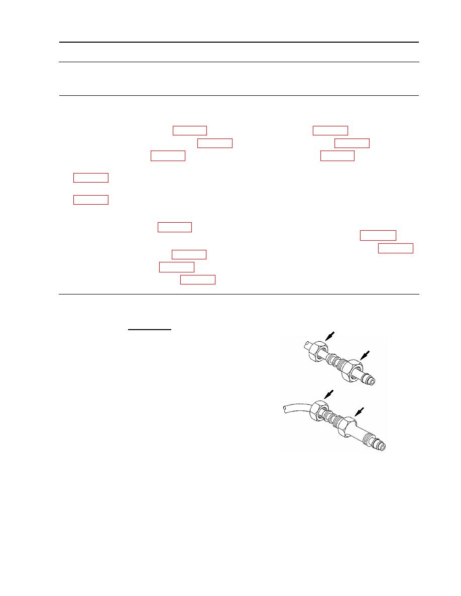
Both ends of each fuel injection
2
tube have a support nut (1) that
must be loosened prior to
loosening the compression nut (2)
[nozzle end] or compression
1
connector (3) [pump end]. The
compression nut or compression
3
connector must be held in place
while loosening the support nut.
Failure to comply may result in
damage to fuel injection tubes.
NOTE
Each fuel injection tube is unique and must be returned to its original
position. Each tube is marked for cylinder location.
WP 0113 00-1
|
||
|
||


