
| Tweet |

Custom Search
|
|

|
||
 TM 9-2815-220-24
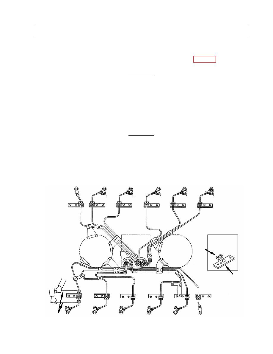
FUEL INJECTION TUBES REPLACEMENT
0113 00
INSTALLATION (Continued)
11. Check that all tube assemblies have 1/8 inch (3.175 mm) minimum clearance to each other at
pump end. Bend tubes as necessary, with bending tools (24) (item 13, WP 0177) to obtain
clearance.
CAUTION
When bending of tube assemblies is required at the pump end, the
compression connector and support nut must be re-torqued. Tighten
compression connector to 35 foot-pounds (48 Nm). Tighten support
nut to 125 inch-pounds (14 Nm).
12. Install 12 lower fairlead halves (28) between tube assemblies and brackets (33) at each
cylinder.
CAUTION
When bending injection tubes is required, be careful not to nick
tubing. The bending tools are designed to allow bending without
nicks.
13. Assure that fairlead halves (28) are aligned with bracket (33) holes and align tube to fit within
1/8 inch (3.175 mm) in any direction with fairlead half. Use two bending tools (24).
Right Bank
Damper End
Typical
(12 places)
28
33
Left Bank
24
WP 0113 00-9
|
||
|
||


