
| Tweet |

Custom Search
|
|

|
||
 TM 9-2815-220-24
FUEL INJECTION PUMP ASSEMBLY REPLACEMENT
0115 00
REMOVAL (Continued)
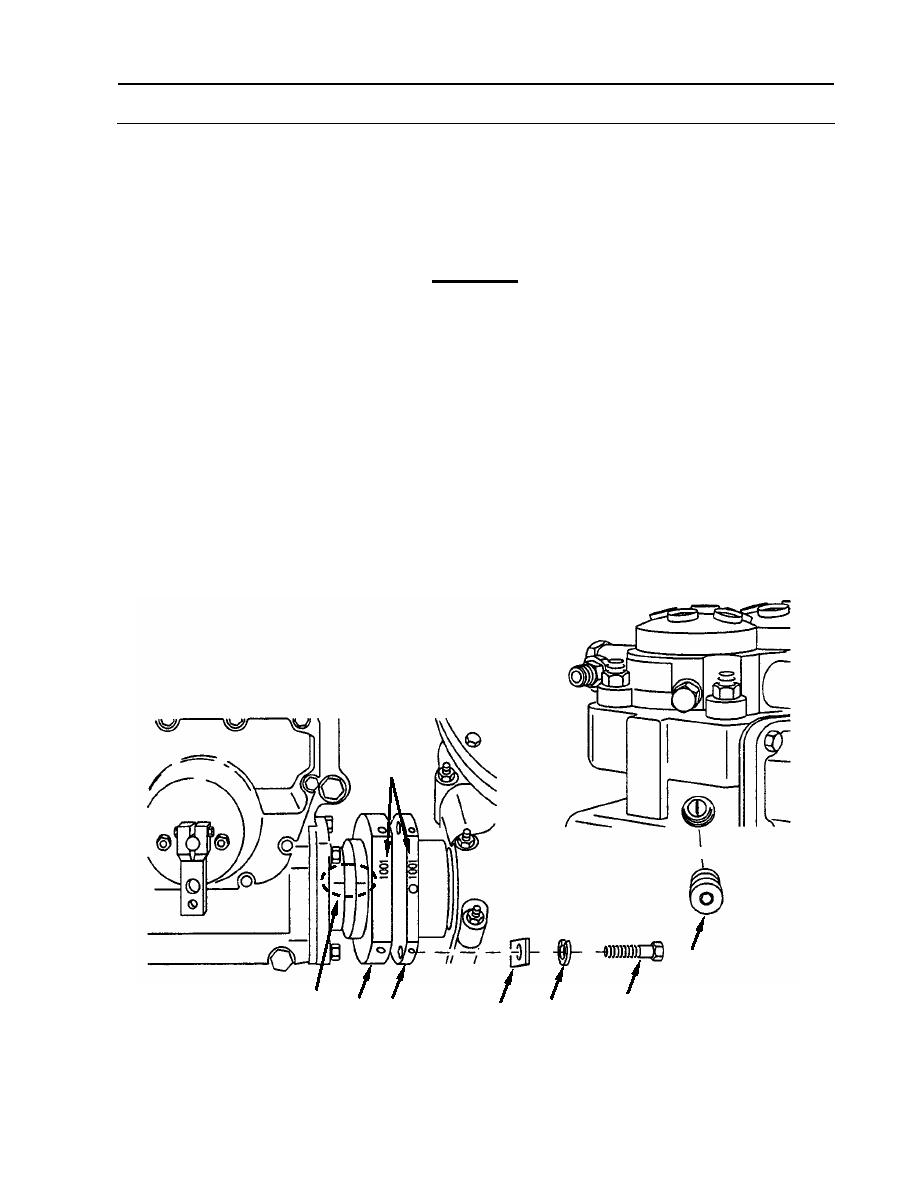
6. Turn flywheel using appropriate turning tool until fuel injection pump coupling sleeves
(16 and 17) are aligned in position shown using timing marks (A).
7. Remove timing plug (18) and look for white tooth in hole. If tooth is not visible, rotate engine
with turning tool another 360 degrees until tooth is visible.
CAUTION
Fuel injection pump coupling sleeves and hubs must be identified with
identical marks to prevent non-mating of parts. The sleeves and hubs
are matched for each assembly and must not be interchanged between
assemblies.
8. Stamp identification marks (B) on both coupling sleeves (16 and 17).
NOTE
Rotate engine enough to remove inaccessible bolt from coupling.
Remove bolt from coupling then rotate engine back to previous
location (with tooth visible in inspection hole and timing marks
aligned).
9. Remove four bolts (19), four lock washers (20), and four spacers (21). Discard lock washers.
10. Separate coupling sleeves (16 and 17).
B
18
A
19
16 17
20
21
WP 0115 00-5
|
||
|
||


