
| Tweet |

Custom Search
|
|

|
||
 TM 9-2815-220-24
FUEL INJECTION PUMP ASSEMBLY REPLACEMENT
0115 00
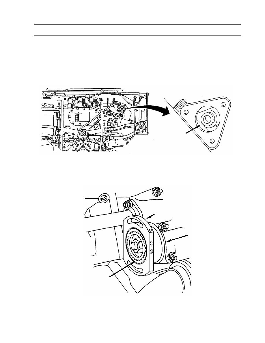
INSTALLATION (Continued)
4. Assure that number one, right bank cylinder, is on the compression stroke (Continued).
c. Check to see that camshaft (34) lobes on cylinder 1R are pointed towards crankshaft.
d. If camshaft (34) lobes do not point towards crankshaft, rotate flywheel 360 degrees until
"1R INJ PORT CLOSE" mark once again is aligned with timing mark and camshaft lobes
on cylinder 1R do point towards crankshaft.
34
5. Push coupling sleeve (17) toward rear fan/accessory drive housing (35) until sleeve clears
hub (36).
17
35
36
WP 0115 00-11
|
||
|
||


