
| Tweet |

Custom Search
|
|

|
||
 TM 9-2815-220-24
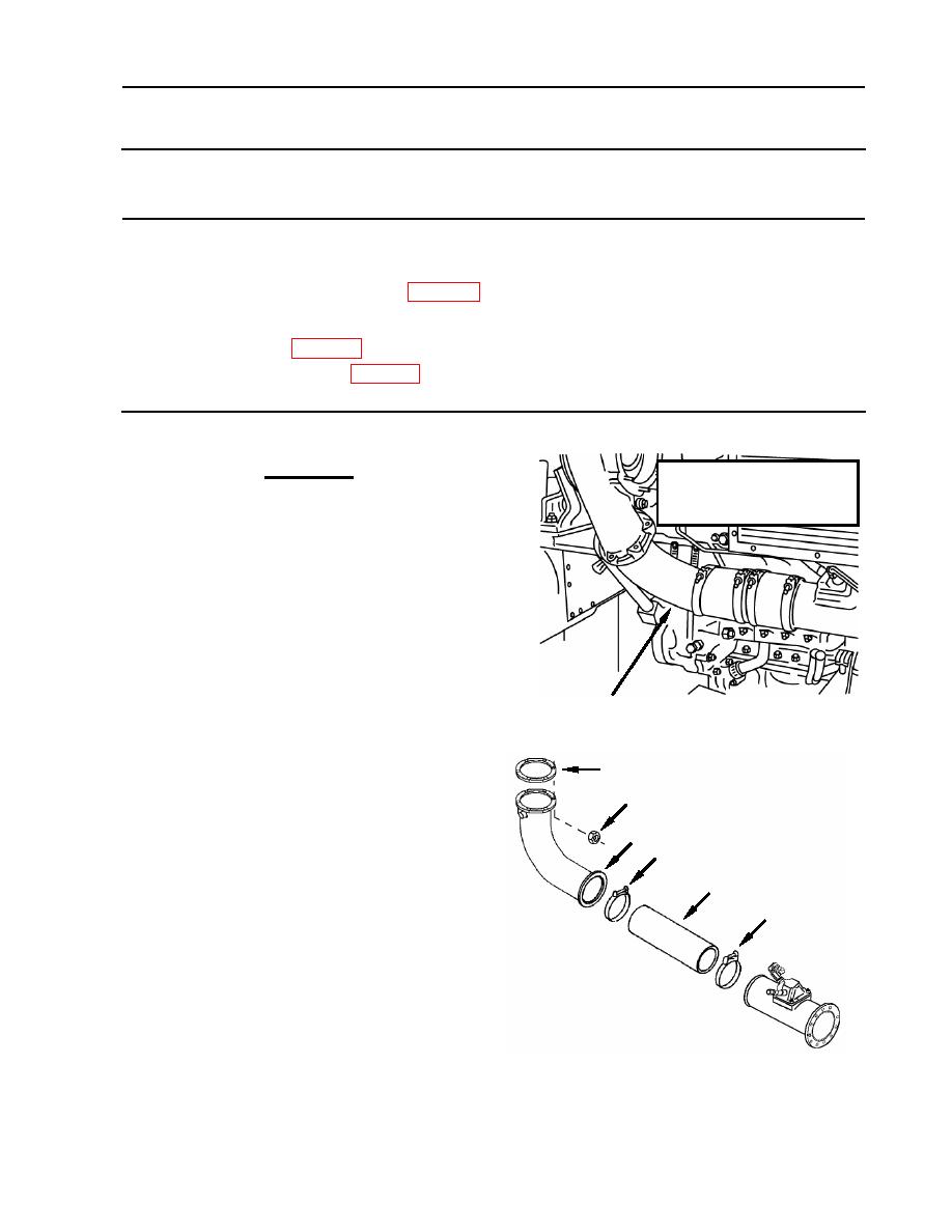
TURBOSUPERCHARGER COMPRESSOR OUTLET ELBOW
REPLACEMENT
THIS WORK PACKAGE COVERS:
Disassembly, Cleaning, Inspection, Repair, and Assembly
INITIAL SETUP:
Tools:
Personnel Required:
General mechanic's tool kit (item 121, WP 0176)
Track Vehicle Repairer (1) 63H10
Mandatory Replacement Parts:
Equipment Conditions:
Gasket (2) (item 309, WP 0175)
Engine removed from vehicle and placed on a
flat stationary surface
Self locking nut (6) (item, 33, WP 0175)
REMOVAL
CAUTION
EARLY MODEL
Early model engines may have a two-
CONFIGURATION
piece hose connection between the
turbocharger compressor outlet
elbow and intake manifold. If your
engine has the two-piece hose
connection, you should replace the
existing (two hose and intermediate
pipe) set-up with the one-piece hose
(part number 11682625). Failure to
comply may lead to premature
Compressor Elbow
engine failure due to dust ingestion.
NOTE
5
Left and right bank turbocharger
3 (six places)
compressor elbows are replaced in a
similar manner. For instructional
4
purposes, the left bank is described.
2
1. Loosen hose (1) clamps (2).
1
2. Remove six self-locking nuts (3) and remove
2
compressor outlet elbow (4) and hose (1) as
an assembly.
3. Separate elbow (4) and clamps (2) from
hose (1).
4. Remove and discard gasket (5).
WP 0120 00-1
|
||
|
||


