
| Tweet |

Custom Search
|
|

|
||
 TM 9-2815-220-24
THROTTLE CONTROL SOLENOID ASSEMBLY AND ASSOCIATED PARTS
REPLACE/REPAIR (2DR)
0123 00
ASSEMBLY
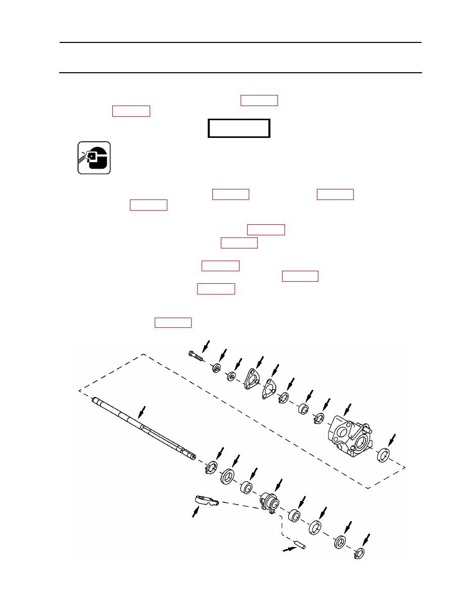
1. Install two new needle bearings (66) (item 22, WP 0175) and a new plain encased seal (67)
(item 275, WP 0175) in solenoid control housing (44).
WARNING
Retaining rings are spring tension devices: take care when removing
or installing them. They can slip or break and become airborne
causing eye damage or other bodily harm.
2. Install solenoid control housing (44) on straight shaft (16) with two flat washers (60 and 65)
pliers (item 81, WP 0176).
3. Install solenoid stop control (57) on pin (58) in solenoid control housing (44).
4. Install a new plain encased seal (63) (item 189, WP 0175) in solenoid housing assembly (12).
5. Install a new retaining ring (62) (item 8, WP 0175) on straight shaft (16) then install solenoid
housing assembly (12) on straight shaft (16) and over solenoid control housing (44).
6. Install new bearing (61) (item 322, WP 0175) in solenoid housing assembly (12) and secure to
straight shaft (16) with a new retaining ring (62) (item 8, WP 0175).
7. Install new gasket (54) (item 188, WP 0175) and access cover (53) on solenoid housing
assembly (12).
8. Secure access cover (53) to housing assembly (12) using three screws (50), with new lock
washers (51) (item 92, WP 0175), and three flat washers (52).
50
51
52 53
54
62
61
62
12
16
63
64
65
66
44
66
67
60
57
59
58
WP 0123 00-11
|
||
|
||


