
| Tweet |

Custom Search
|
|

|
||
 TM 9-2815-220-24
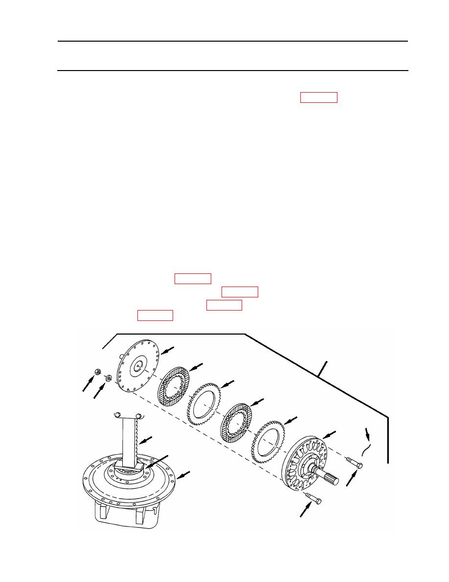
FAN DRIVE CLUTCH ASSEMBLY AND ASSOCIATED PARTS
REPLACE/REPAIR
0129 00
ASSEMBLY (Continued)
7. Lubricate four clutch disks (38, 39) with lubricating oil (item 21, WP 01073).
8. Install four clutch disks (38, 39) in fan drive hub assembly (32) in the order shown.
9. Install flange (31) over clutch disks and on fan drive hub assembly (32) being sure to align
screw holes.
NOTE
Compressing the clutch assembly can be accomplished by temporarily
using undersized screws with flat washers and nuts to draw the
assembly together.
10. Assemble clutch assembly (26).
a. Equally space four temporary screws (45) through friction clutch assembly (26) and secure
using four flat washers (46) and nuts (47). Alternately tighten the four nuts (47) to draw
the friction clutch (26) together.
b. Install 12 screws (34) and torque to 150-160 inch-pounds (17-18 Nm).
c. Remove four nuts (47), flat washers (46) and screws (45).
d. Install remaining 4 screws (34) and torque to 150-160 inch-pounds (17-18 Nm), using
torque wrench (item 124, WP 0176).
e. Install new locking wire (33) (item 44, WP 0173).
11. Press new ball bearing (29) (item 295, WP 0175) in access cover (25) using an arbor
press (30) (item 8, WP 0176).
31
26
39
38
39
47
46
38
33
32
30
29
25
34
45
WP 0129 00-13
|
||
|
||


