
| Tweet |

Custom Search
|
|

|
||
 TM 9-2815-220-24
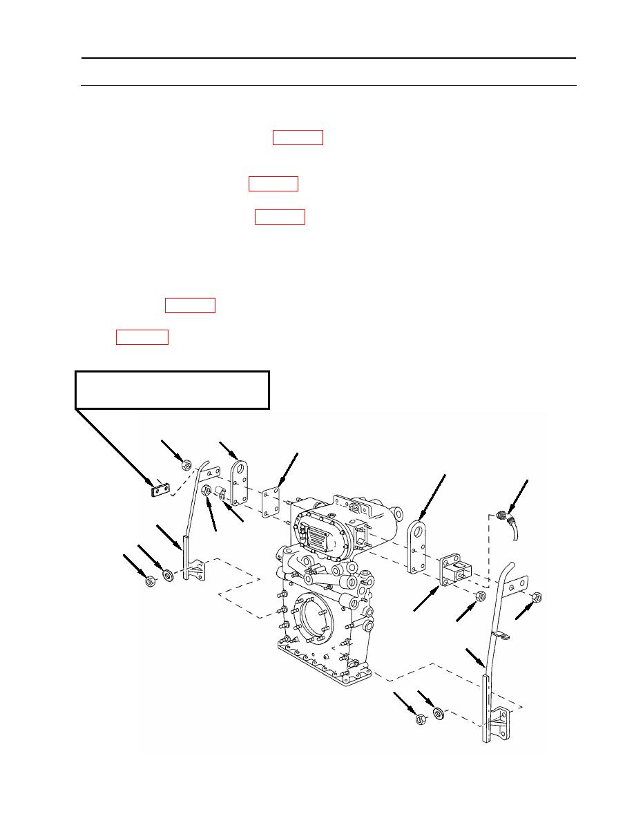
FRONT LIFTING EYES AND GUIDES REPLACEMENT
0132 00
INSTALLATION
1. Install left installation guide bar (1) and lifting eye (2).
a. Place new gasket (7) (item 182, WP 0175) and lifting eye (2) over studs on left side of
damper housing as illustrated.
b. Put left installation guide bar (1) in place and secure on lower studs with two new self-
locking nuts (5) (item 34, WP 0175) using flat washers (6).
c. Put cushioned clamp (4) securing fuel return hose in place and secure with four new self-
locking nuts (3) (item 140, WP 0175).
2. Install right installation guide bar (8), lifting eye (2) and hour meter (9).
a. Put lifting eye (2) in place on right side of damper housing.
b. Put hour meter (9) in place on damper housing.
c. Put right installation guide bar (8) in place and secure with two new self-locking nuts (5)
(item 34, WP 0175) using two flat washers (6) at lower end of installation guide bar.
d. Secure top end of installation guide (8) bar with four new self-locking nuts (3) (item 140,
e. Connect hour meter (9) electrical connector (10).
2DR spacer plate: used in place of
installation guide bar.
3
2
7
2
10
1
4
3
6
5
9
3
3
8
6
5
END OF WORK PACKAGE
WP 0132 00-3 (4 blank)
|
||
|
||


