
| Tweet |

Custom Search
|
|

|
||
 TM 9-2815-220-24
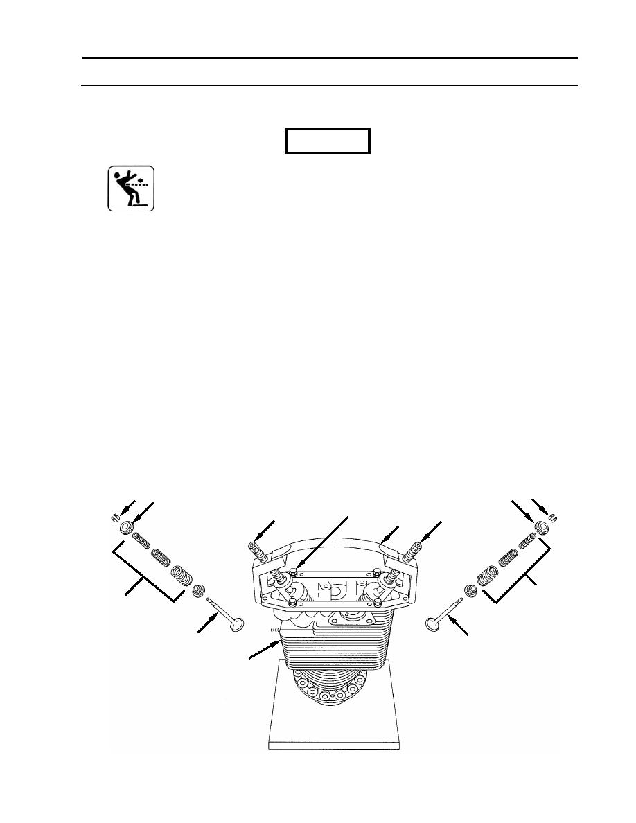
CYLINDER ASSEMBLY REPAIR
0135 00
DISASSEMBLY (Continued)
WARNING
Valves and locks are under heavy spring tension. Exercise extreme
care when removing locks, seats, and springs. Each valve spring set
consists of three separate springs. Failure to comply may result in
injury.
3. Remove exhaust valve (6).
a. Compress exhaust valve springs (7) by turning screw (8).
b. Remove two valve spring locks (9) from the groove in exhaust valve (6) stem.
c. Tap exhaust valve spring retainer (10) to free valve spring locks (9).
d. Carefully loosen screw (8) to release valve springs (7).
4. Remove intake valve (11).
a. Compress intake valve springs (12) by turning screw (13).
b. Remove two valve spring locks (9) from the groove in intake valve (11) stem.
c. Tap valve spring retainer (14) to free valve spring locks (9).
d. Carefully loosen screw (13) to release valve springs (12).
5. Remove valve lifter assembly (3).
a. Remove four rocker cover screws (4) with flat washers (5).
b. Remove valve lifter assembly (3) from cylinder assembly (1).
9
10
9 14
4,5
13
8
3
7
12
11
6
1
WP 0135 00-3
|
||
|
||


