
| Tweet |

Custom Search
|
|

|
||
 TM 9-2815-220-24
CYLINDER ASSEMBLY REPAIR
0135 00
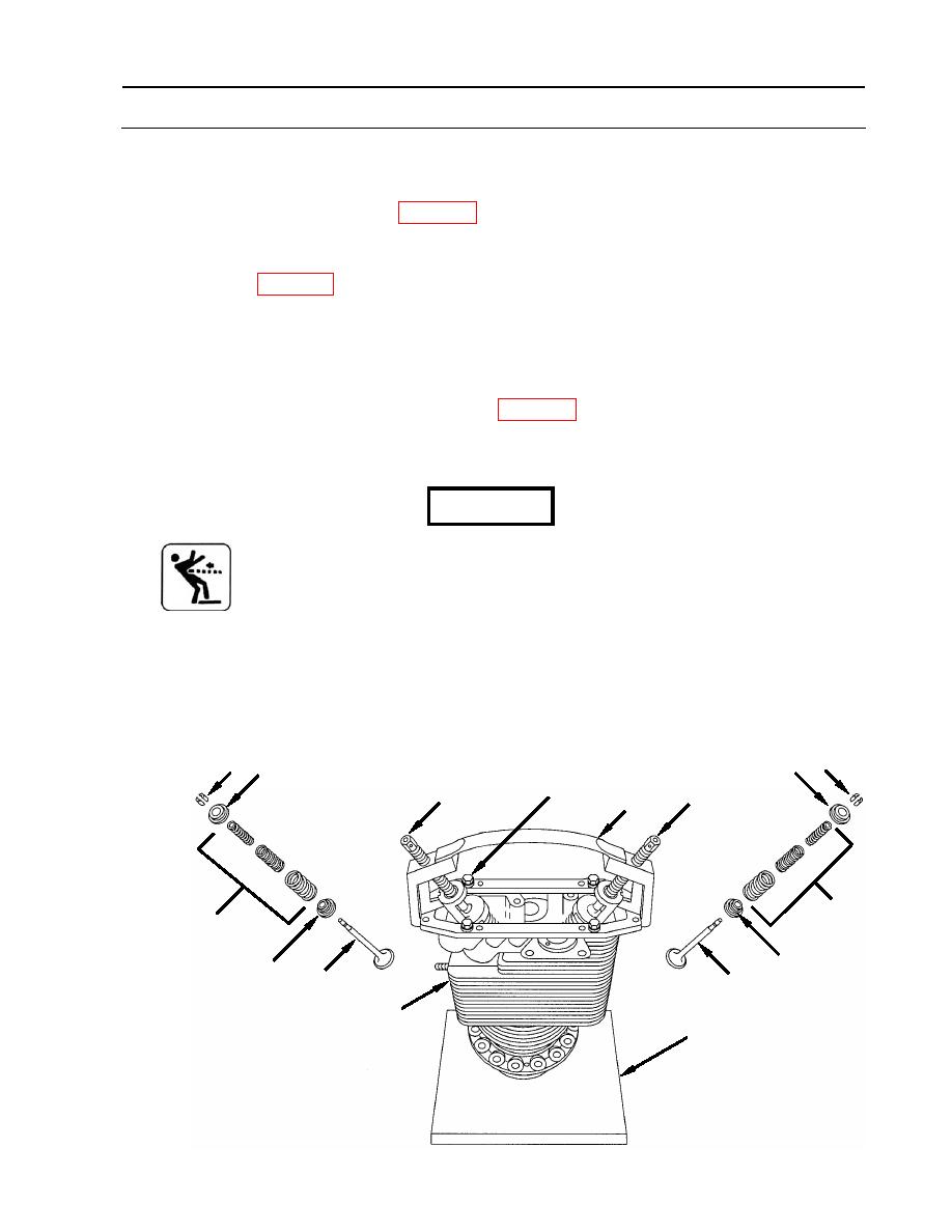
ASSEMBLY
1. Install valves.
a. Apply lubricating oil (item 21, WP 0173) to valve stems and install intake valve (11) and
exhaust valve (6) in their respective guides in cylinder assembly (1).
b. Hold valves in position and place cylinder (1) on valve removing and inserting stand (2)
(item 112, WP 0176).
c. Install exhaust valve rotor (15), outer, intermediate, and inner exhaust valve springs (7),
and exhaust valve spring retainer (10) over the exhaust valve (6) stem.
d. Install intake valve spring seat (16), outer, intermediate, and inner intake valve
springs (12), and intake valve spring retainer (14) over the intake valve (11) stem.
e. Position valve lifter assembly (3) (item 72, WP 0176) on cylinder assembly (1) and secure
with four 5/16 x 1.375 (7.9375 x 34.9250 mm), rocker cover screws (4) and four 5/16-inch
(7.9375 mm) flat washers (5).
WARNING
Valves and locks are under heavy spring tension. Exercise extreme
care when installing locks, seats, and springs. Each valve spring set
consists of three separate springs. Failure to comply may result in
injury.
f. Compress exhaust and intake valve springs (7,12) and retainers (10,14) with screws (8 and
13) then install two valve spring locks (9) in the groove of each valve (6,11) stem.
g. Release valve spring compression and remove four rocker cover screws (4) with flat
washers (5) and valve lifter assembly (3) from cylinder (1).
h. Remove cylinder (1) from valve removing and inserting stand (2).
10 9
9 14
4,5
13
8
3
7
12
15
16
11
6
1
2
WP 0135 00-17
|
||
|
||


