
| Tweet |

Custom Search
|
|

|
||
 TM 9-2815-220-24
CRANKSHAFT REPLACE/REPAIR
0139 00
INSTALLATION (Continued)
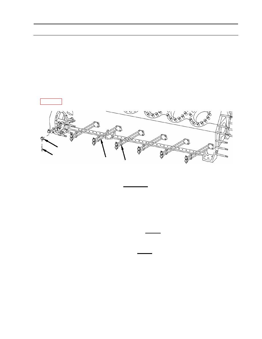
NOTE
To avoid interference with the starter driven gear shaft, it is necessary
to install lower number 7 tie-rod from the right side of crankcase.
Care should be taken so tie-rods extend equally on both sides of
crankcase.
7. Install 14 tie-rods (1) through crankcase.
8. Install seven washer plates (5), 14 slotted nuts (4), and 14 new cotter pins (3) (item 28,
4
3
1
5
9. Install seven washer plates (5) and 14 slotted nuts (4) onto opposite end of tie-rods. Do not
tighten slotted nuts nor install new cotter pins at this time.
CAUTION
The procedure for tightening main bearing cap nuts incorporates
both torque and stud stretch. The untorqued height of the studs must
first be measured, then the studs are torqued incrementally to a final
value, and finally the stretch of the stud is measured. Stud stretch is
defined as the difference between the untorqued height and the
torqued height of the studs.
Any stud that exceeds the maximum stretch (0.024 inch, or
0.6096 mm) prior to obtaining the minimum torque (58 foot-pounds,
or 79 Nm) must be replaced.
prior to obtaining minimum stretch (0.019 inch, or 0.4826 mm) must
be replaced.
Do not disturb dial indicator setting or position used for checking stud
stretch. Incorrect stretch measurement will result if indicator setting
is changed - which could result in premature failure of engine parts.
WP 0139 00-21
|
||
|
||


