
| Tweet |

Custom Search
|
|

|
||
 TM 9-2815-220-24
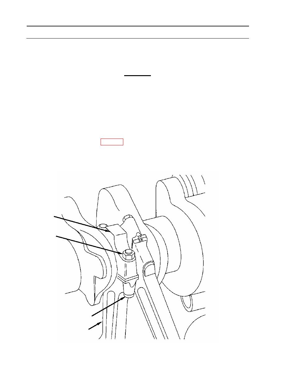
CONNECTING ROD ASSEMBLY REPAIR
0143 00
ASSEMBLY (Continued)
3
Position connecting rod (1) on crankshaft in proper location according to identification
number.
CAUTION
Connecting rod numbers begin at the damper end of the crankshaft.
Right bank rods are installed on the damper end of each crankshaft
journal and left bank rods are on the flywheel end. All location
numbers must be visible from the oil pan opening when crankshaft
and rods are installed in the crankcase.
4. Position connecting rod cap (4) with bearing installed on journal, and mate it with the
corresponding rod (1).
5. Secure rod (1) and cap (4) with two rod bolts (8) and hexagon nuts (3).
a. Apply Lubriplate (item 23, WP 0173) to rod bolt (8) threads and nut (3) seat.
b. Tighten both nuts alternately to 100-150 inch-pounds, then to 600-650 inch-pounds (50-54
foot-pounds, or 68-73 Nm), and finally to 1250-1300 inch-pounds (104-108 foot-pounds,
or 141-147 Nm).
4
3
8
1
WP 0143 00-12
|
||
|
||


