
| Tweet |

Custom Search
|
|

|
||
 TM 9-2815-220-24
CAMSHAFT, DRIVE GEARS, AND ASSOCIATED PARTS REPLACEMENT
0146 00
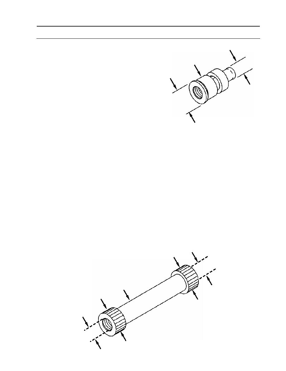
INSPECTION
B
1. Measure and record outside diameter (A) of
lubrication fitting (9). Measurement will
9
also be used for fit [0.0020 inch, L
(0.0508 mm, L)] to bevel gear shaft (7).
A
a. Reject lubrication fitting (9) if dimension
is less than 1.2695 inches (32.2453 mm).
2. Measure and record outside diameter (B) of
lubrication fitting (9). Measurement will
also be used for fit [0.0050 inch, L
(0.127 mm, L)] to quill shaft (5).
a. Reject lubrication fitting (9) if
dimension (B) is less than 0.6265 inch (15.9131 mm).
3. Inspect quill shaft (5).
a. Visually inspect quill shaft (5).
(1) Check splines (C, D). Look for obvious damage (severe wear, broken teeth, or heat
damage). If any is found, discard quill shaft (5).
b. Measure and record inside diameter (E) at both ends of quill shaft (5). Reject shaft if
dimension is greater than 0.6315 inch (16.0401 mm).
c. Measure outside diameter (C) of quill shaft spline at threaded end over two 0.0800-inch
(2.032-mm) pins. Reject shaft if dimension is less than 1.2852 inches (32.64408 mm).
d. Measure outside diameter (D) of quill shaft spline at non-threaded end over two 0.0800-
inch (2.032-mm) pins. Reject shaft if dimension is less than 1.1184 inches
(28.40736 mm).
e. Calculate fit of lubrication fitting (9) to quill shaft (5).
(1) Subtract dimension (B) measured in step 2 from dimension (E).
(2) Reject both pieces if fit is looser than 0.0050 inch (0.127 mm).
E
D
5
C
E
WP 0146 00-5
|
||
|
||


