
| Tweet |

Custom Search
|
|

|
||
 TM 9-2815-220-24
FUEL INJECTION ADVANCE CONTROL REPAIR
0161 00
ASSEMBLY (Continued)
CAUTION
Vane must have 0.0010 to 0.0015-inch (0.0254 to 0.0381 mm) end
clearance with vane housing. Improper clearance will affect
operation of advance unit.
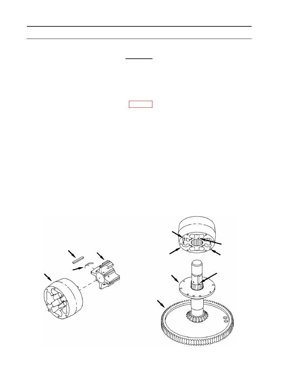
7. Install vane (24) in housing (21).
a. Position vane (24) into housing (21).
b. Install eight new seals (26) (item 174, WP 0175) into slots in vane.
c. Slide springs (25), (item 174.1) between seals (26) and vane (24) as shown. Assure that
springs are not exposed, but recessed slightly beyond end of vane.
NOTE
Dowel pins and holes will align in two positions. However, bolt holes
in the cover and housing will align in one position only. Make certain
that the cover and housing are correctly positioned so that bolt holes
are aligned (use scribed line as described in step 1 of Disassembly).
8. Install housing (21) onto cover (7).
a. Assure that alignment dot (A) on housing spline aligns with alignment dot (B) on gear
shaft spline.
b. Install housing (21), vane (24), springs (25), and seals (26) over bevel gear shaft (27) and
onto cover (7) as an assembly.
c. Position housing (21) onto cover (7) so that dowel pins (23) align with pin holes, and bolt
holes in housing (21) align with threaded holes in cover (7).
23
A
26
24
21
23
21
25
B
7
27
WP 0161 00-16
|
||
|
||


