|
|
|
|

|
TM 9--2815--247--34
0026 00--8
ROCKER ARM COVER ASSEMBLY REPLACEMENT -- CONTINUED
0026 00
Installation
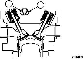
1. Rotate crankshaft until two camshaft lobes (37) for intake and exhaust valves are pointed towards the crankshaft.
Figure 9
INTAKE
EXHAUST
37
37
2. Apply a light film of sealant on mating surface of valve rocker arm cover assembly (13).
CAUTION
Identifying numbers on rocker arm cover assembly and
cylinder must correspond. Camshaft bearing half must
be installed in cover. Valve rocker arm rollers must con-
tact base circle of camshaft and lip of preformed inter--
cylinder sleeves must not be folded under rocker arm
cover assembly.
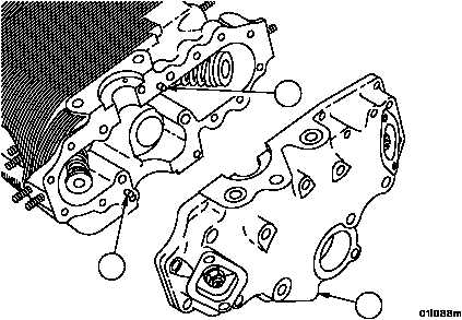
3. Tap rocker arm cover assembly (13) gently to position rocker arm cover assembly (13) over pins (38).
Figure 5
38
38
13
|
|
|
|
|
Privacy Statement -
Copyright Information. -
Contact Us