TM 9--2815--247--34
0037 00--18
FUEL INJECTOR TUBES, BRACKETS, AND ASSOCIATED PARTS --
CONTINUED
0037 00
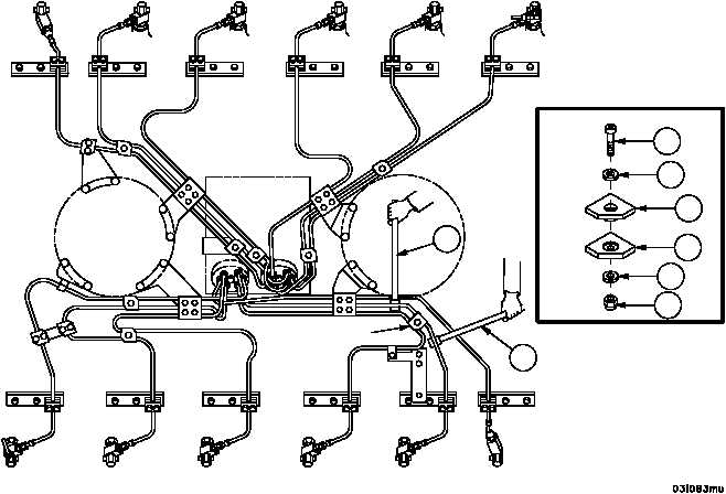
Installation -- Continued
45. Install floating clamp (DETAIL G) in location shown in illustration.
CAUTION
Where bending tubes is required, be careful not to nick
tubing. The bending tools are designed to allow bending
without nicks.
46. Using two bending tools (72), align tubes to fit within 1/8 inch (3.175 mm) in any direction with upper and lower
clamps.
47. Apply a small amount of lubricant (item 12, WP 0100 00) to threads of socket head screw (32).
48. Install upper clamp half (35), lower clamp half (36), socket head screw (32), two flat washers (34), and new self--
locking nut (33) (DETAIL G).
49. Tighten socket head screw (32) to 75--100 lb--in (8.5--11.3 NSm).
Figure 36
RIGHT BANK
LEFT BANK
FLYWHEEL
END
DAMPER
END
G
G
32
33
34
34
35
36
72
72
|
|