|
|
|
|

|
TM 9--2815--247--34
0048 00--3
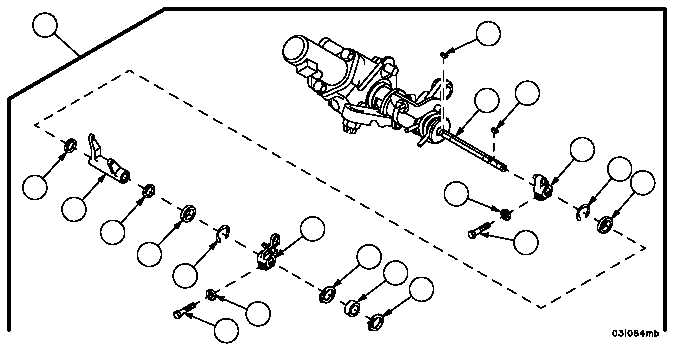
THROTTLE CONTROL SOLENOID ASSEMBLY AND ASSOCIATED PARTS
REPAIR -- CONTINUED
0048 00
Disassembly
WARNING
1. Place throttle control assembly (13) in a machinist vise and remove retaining ring (15) from straight shaft (16).
Discard retaining ring.
2. Remove bearing (17) using a suitable puller and remove retaining ring (18) from straight shaft (16). Discard re-
taining ring.
3. Remove screw (19) and lockwasher (20) from throttle lever assembly (8). Discard lockwasher.
4. Remove throttle lever assembly (8) and woodruff key (21) from straight shaft (16). Discard woodruff key.
5. Remove retaining ring (22) and flat washer (23) from straight shaft (16). Discard retaining ring.
6. Remove fuel shut--off lever assembly (24) from straight shaft (16).
7. Remove two plain seals (25) from fuel shut--off lever assembly (24).
8. Remove flat washer (26) and retaining ring (27) from straight shaft (16). Discard retaining ring.
9. Remove screw (28) and lockwasher (29) from throttle lock control lever assembly (30). Discard lockwasher.
10. Remove throttle lock control lever assembly (30) and woodruff key (31) from straight shaft (16). Discard woodruff
key.
Figure 47
31
16
21
30
27
26
28
15
17
18
8
20
19
22
24
23
25
25
13
29
|
|
|
|
|
Privacy Statement -
Copyright Information. -
Contact Us