TM 9--2815--247--34
0048 00--19
THROTTLE CONTROL SOLENOID ASSEMBLY AND ASSOCIATED PARTS
REPAIR -- CONTINUED
0048 00
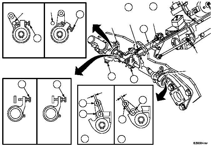
Adjust
1. With the throttle linkage in full throttle position (91), clearance between stop pin of remote control lever (8) and
pump drive adapter assembly (14) must be 1/8 inch (3.175 mm) nominal.
2. With the throttle linkage in idle position (92), clearance between stop pin of remote control lever (8) and pump
drive adapter assembly (14) must be 3/16 inch (4.7625 mm) minimum.
3. When the foregoing clearances are not met, loosen lock nuts (93 and 94) on control rod assembly (4), and adjust
as necessary to obtain required clearance.
4. Tighten lock nuts (93 and 94) after adjustment.
Figure 47
IDLE
POSITION
FULL
THROTTLE
POSITION
STOP
PIN
STOP
PIN
SOLENOID
SPEED
CONTROL
POSITION
IDLE
POSITION
FULL
THROTTLE
POSITION
3/16 IN. MIN
1/8 IN. NOMINAL
STOP
PIN
RIGHT
HAND
THREAD
LEFT
HAND
THREAD
STOP
PIN
SOLENOID
SPEED
CONTROL
IDLE
POSITION
THROTTLE
OPERATING
LEVER
4
94
93
28
28
56
56
8
14
92
91
8
14
56
28
FULL THROTTLE
NOTE
The idle adjusting screw (28) and the solenoid speed
control screw (56) must not be set until engine is installed
and tested.
|
|