TM 9--2815--247--34
0054 00--3
FAN DRIVE CLUTCH ASSEMBLY AND ASSOCIATED PARTS REPAIR --
CONTINUED
0054 00
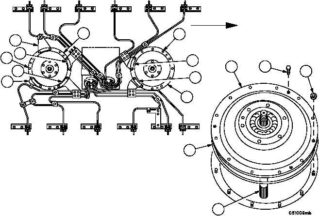
Removal -- Continued
2. Remove double angle brackets (6, 7, 8, 9 and 10), and angle bracket (11). Refer to WP 0037 00.
3. Remove eight (on front fan clutch) or four (on rear fan clutch) self--locking nuts (12) securing access cover (13).
Discard self--locking nuts.
NOTE
Three of the (5/16--24) machine bolts removed from seal
housing may be used as jack screws to remove access
cover.
4. Install three machine bolts as jack screws (14) in threaded holes provided in access cover (13).
5. Alternately tighten jack screws (14) and remove access cover (13) and friction clutch (15) as a unit.
6. Remove jack screws (14) from access cover (13).
7. Remove preformed packing (16). Discard packing.
Figure 55
10
9
11
8
12
13
13
12
6
7
FORWARD
13
14
15
16
12
|
|