TM 9--2815--247--34
0004 00--12
THEORY OF OPERATION -- CONTINUED
0004 00
CRANKCASE BREATHER AND FIRE EXTINGUISHER SYSTEMS
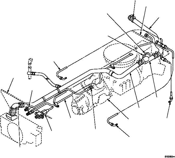
Crankcase Breather System A large diameter breather tube is run through the engine from the top of the damper
housing to the back of the engine (Figure 1--12). The engine breathes from the top of the damper housing. The
engine is shipped with a breather extension tube to facilitate connection to the RH bank turbo tail pipe. At the bot-
tom of the extension tube is a small trap where oil drains to the RH bank corner of the oil pan.
Fire Extinguisher System The engine is equipped with a fire extinguisher tube located in the “V” (Figure 1--12).
This tube is connected to the engine compartment fire extinguisher system. The tube has small holes drilled along
the entire length to direct the carbon dioxide (CO2) fire extinguisher fluid in predetermined directions around cylin-
ders, fuel metering pump, and inter--cylinder components in case of fire.
FRONT
SHROUD
TO AFTERCOOLER
BYPASS VALVE
HOUSING
0.030 IN. RESTRICTOR PLATE
BETWEEN BREATHER TEE
AND ACCESSORY DRIVE
HOUSING
FROM CRANKCASE AND
ACCESSORY DRIVE HOUSING
REAR SHROUD
TO LEFT EXHAUST PIPE
REAR CRANKCASE
BREATHER TUBE
FROM CRANKSHAFT
DAMPER AND OIL FILTER
HOUSING
FUEL RETURN
TO VEHICLE
FUEL TANK
FIRE EXTINGUISHER
TUBE
TO AFTERCOOLER
BYPASS VALVE
HOUSING
CRANKCASE
BREATHER
DRAIN
CRANKCASE
BREATHER
TUBE
CRANKCASE
BREATHER
TUBE TEE
FUEL METERING PUMP
FUEL CUT--OFF LEAD
FUEL METERING
PUMP
FUEL METERING PUMP FUEL
CUT--OFF CONNECTOR
Figure 1--12. Engine Crankcase Breather, Fire Extinguisher System and Fuel Return
|
|