TM 9--2815--247--34
0059 00--6
CYLINDER HEAD ASSEMBLY REPLACEMENT -- CONTINUED
0059 00
Installation
NOTE
Do not remove crankcase protectors until connecting rods
have been removed or cylinder head assemblies are be-
ing reinstalled.
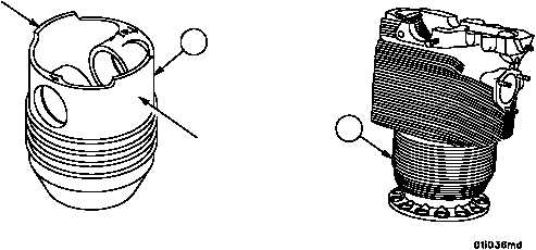
The pistons (11) are marked for identification to aid in
installing the pistons in the proper position. The piston
pin boss is stamped with an arrow and the cylinder head
assembly location to identify the cylinder from which the
piston was removed and to assure piston will be returned
to its original cylinder head assembly. The arrows on the
piston pin bosses are pointed up, or to exhaust port. Cyl-
inder head assemblies (1) are stamped with position
markings at the intake valve side (bottom) of valve rocker
arm cover flange. Markings of any piston or cylinder
head assemblies must be renewed if position marks and/
or arrows are not entirely legible. Replacement piston
must be marked to the corresponding cylinder head as-
sembly it is to be used with. Always keep piston pin with
its respective piston.
Wash cylinder bores thoroughly just prior to engine as-
sembly, using a power brush with hot 160°F (71°C) soapy
water. Cylinder bores should then be oiled to prevent
rust.
Figure 8
EXHAUST PORT
SIDE OF PISTON
INTAKE PORT
SIDE OF PISTON
1
11
|
|