TM 9--2815--247--34
0061 00--5
CYLINDER HEAD ASSEMBLY REPAIR -- CONTINUED
0061 00
Cleaning
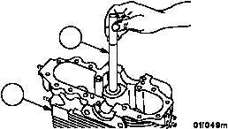
1. Clean cylinder head assembly (1) and associated parts. Refer to WP 0012 00.
2. Remove heavy carbon deposits from combustion chamber with a scraper or blunt tool which will not nick or
scratch the surface. Remove only the heavy carbon deposits. Surface need not be cleaned to a mirror finish.
3. Clean carbon from fuel injector nozzle seat using nozzle carbon cutter (16).
4. Soak cylinder head assembly (1) in carbon--removing compound to remove carbon and other foreign material
from dome and valve ports.
Figure 5
1
16
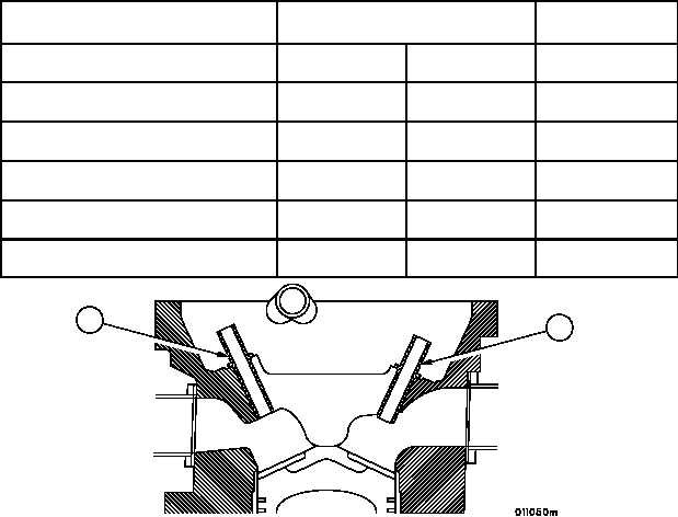
Inspection
1. Inspect valve guides (17 and 18) for cracks, galling, erosion, or scuffing.
2. Check guides against limits specified in the following table. If guides are out of limits, they must be replaced.
POINT OF MEASUREMENT
SIZES AND FITS OF NEW PARTS
inches (mm)
WEAR LIMITS
Inside diameter of intake valve guide
0.4995
(12.6873)
0.5005
(12.7127)
0.5035 (12.7889)
Outside diameter of intake valve stem
0.4975
(12.6365)
0.4980
(12.6492)
0.4970 (12.6238)
Fit of intake valve stem in guide
0.0015L
(0.0381)
0.0030L
(0.0762)
0.0065L (0.1651)
Inside diameter of exhaust valve
guide
0.5615
(14.2621)
0.5625
(14.2875)
0.5655 (14.3637)
Outside diameter of exhaust valve
stem
0.5570
(14.1478)
0.5580
(14.1732)
0.5565 (14.1351)
Fit of exhaust valve stem in guide
0.0035L
(0.0889)
0.0055L
(0.1397)
0.0090L (0.2286)
Figure 5
18
17
|
|