|
|
|
|

|
TM 9--2815--247--34
0061 00--10
CYLINDER HEAD ASSEMBLY REPAIR -- CONTINUED
0061 00
Repair -- Continued
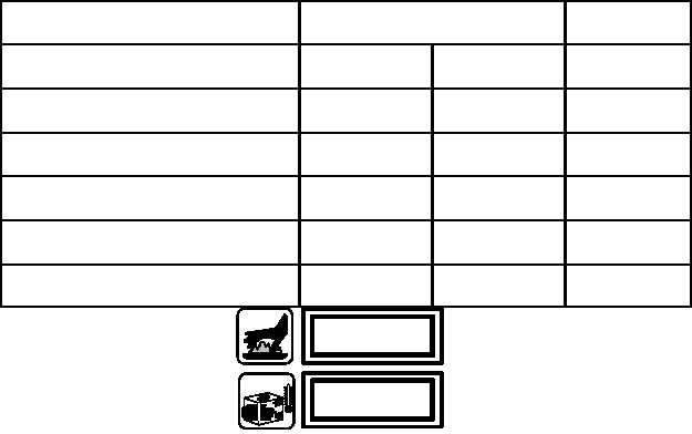
6. Check valve guide bores in cylinder head assembly (1). If not within the following limits, cylinder head assembly
(1) must be replaced.
POINT OF MEASUREMENT
SIZES AND FITS OF NEW PARTS
inches (mm)
WEAR LIMITS
Outside diameter of intake valve guide
0.6890
(17.5006)
0.6895
(17.5133)
none
Inside diameter of intake valve guide
bore in cylinder head
0.6870
(17.4498)
0.6880
(17.4752)
none
Fit of intake valve guide in bore
0.0010T
(0.0254)
0.0025T
(0.0635)
none
Outside diameter of exhaust valve guide
0.7525
(19.1135)
0.7530
(19.1262)
none
Inside diameter of exhaust valve guide
bore in cylinder
0.7495
(19.0373)
0.7505
(19.0627)
none
Fit of exhaust valve guide in bore
0.0020T
(0.0508)
0.0035T
(0.0889)
none
WARNING
WARNING
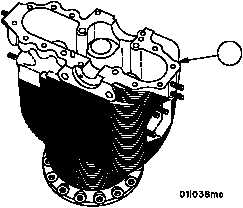
7. Heat cylinder assembly to 350°F (176°C) maximum and chill valve guides for one hour minimum in dry ice or
three hours minimum at --40°F (--40°C) before installing.
NOTE
The intake and exhaust valve guides are installed in the
cylinder in the same manner. A separate replacer is used
for each.
Figure 5
1
|
|
|
|
|
Privacy Statement -
Copyright Information. -
Contact Us