|
|
|
|

|
TM 9--2815--247--34
0068 00--3
SPUR GEAR (ACCESSORY DRIVE) REPLACEMENT-- CONTINUED
0068 00
Removal -- Continued
WARNING
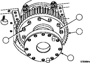
4. Cut lockwire (7) securing 12 screws (8). Discard lockwire.
5. Remove 12 screws (8) and spur gear (9) from crankshaft (10).
Figure 7
9
8
7
10
Inspection
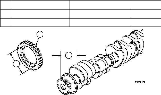
1. Visually inspect spur gear (9). Refer to WP 0012 00.
2. Measure spur gear (9) and replace if it does not meet the following limits:
REF
NO.
POINT OF MEASUREMENT
SIZES AND FITS OF NEW PARTS
inches (mm)
WEAR LIMITS
11
Outside diameter of accessory drive
gear mounting flange on crankshaft
9.7480
(247.5992)
9.7500
(247.65)
9.7470
(247.5738)
12
Inside diameter of crankshaft pilot
bore in accessory drive gear
9.7500
(247.65)
9.7520
(247.7008)
9.7530
(247.7262)
Figure 7
9
12
11
|
|
|
|
|
Privacy Statement -
Copyright Information. -
Contact Us