TM 9--2815--247--34
0069 00--9
PISTONS, RINGS, AND ASSOCIATED PARTS REPAIR -- CONTINUED
0069 00
Inspection -- Continued
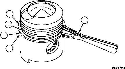
14. Insert remover and replacer (9) in end gap of oil control ring (4) and install in bottom piston ring groove (8).
15. Install compression ring (3) in piston ring groove (7) in the same manner.
Figure 8
4
7
8
9
HIDDEN
HIDDEN
3
NOTE
Excessive side clearance indicates worn rings and/or worn pis-
ton grooves. Less than normal clearance indicates probable
damage or breakage at the ring land.
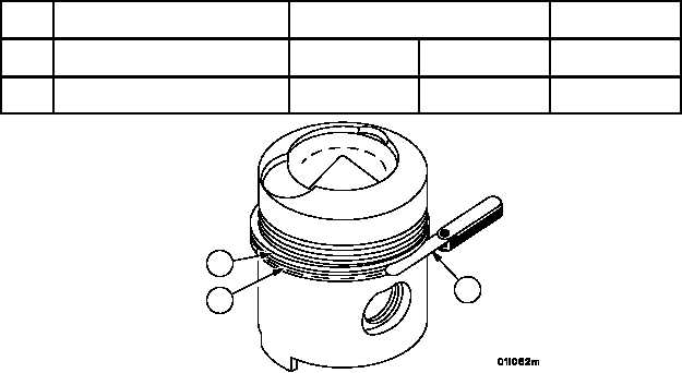
16. Measure side clearance of the bottom two rings (3 and 4) with thickness gauge (22). Mark rings for replacement
that do not meet the following limits.
REF
NO.
POINT OF MEASUREMENT
SIZES AND FITS OF NEW PARTS
inches(mm)
WEAR LIMITS
3
Side clearance between interme--
diate compression ring and piston
0.0045 (0.1143)
0.0025 (0.0635)
0.0100 (0.254)
4
Side clearance between oil control
ring and piston
0.0035 (0.0889)
0.0015 (0.0381)
0.0055 (0.1397)
Figure 8
3
4
24
|
|