TM 9--2815--247--34
0070 00--5
CONNECTING ROD ASSEMBLY AND ASSOCIATED PARTS REPAIR --
CONTINUED
0070 00
Inspection -- Continued
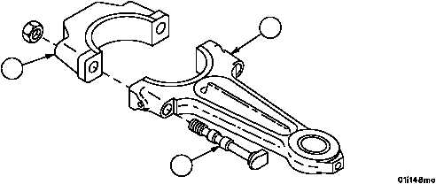
5. Inspect rod bolts (13) for damaged threads, galled pilot diameters, cracks, scratches or any evidence of stretch-
ing. Replace any damaged bolts.
6. Check that bolts (13) fit snugly in rod (3) and cap (2). Replace bolts that have more than 0.0009--inch (0.02286
mm) clearance.
Figure 8
2
13
3
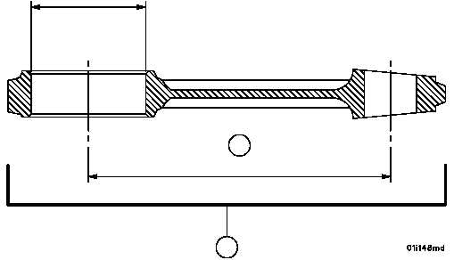
7. Check the dimension between centerline of small and large end bores (14) of connecting rod assembly (9). This
dimension must be 10.998 to 11.002 inches (279.3492--279.4508 mm). Destroy any rod that does not meet this
limit to ensure it will not be reused in an engine.
Figure 8
10.998 MIN. (279.3492 MM)
11.002 MAX. (279.4508 MM)
4.0941 MIN.
(103.99014 MM)
4.0946 MAX.
(104.00284 MM)
TAKE HALF OF THE CONNECTING ROD BORE
DIMENSION OF 4.0941 IN. (103.99014 MM)
TO 4.0946 IN. (104.00284 MM) TO ACHIEVE
10.998 IN. (279.3492 MM) TO 11.002 IN.
(279.4508 MM) BETWEEN CENTERS.
14
9
|
|