TM 9--2815--247--34
0072 00--4
VALVES AND ASSOCIATED PARTS REPAIR -- CONTINUED
0072 00
Repair
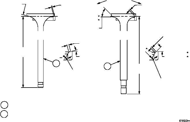
1. Discard valves (1 and 2) which do not conform to the limits specified under inspection, or whose faces are badly
warped, cracked, pitted, or burned.
2. Discard valves (1 and 2) having badly pitted, scored, or scratched stems or locking grooves.
3. Reface slightly pitted or burned valves (1 and 2) that do not have 360° of contact revealed at inspection. Reface
to the specifications shown on illustration.
4. Recheck valves (1 and 2) for 360° contact. Repeat inspection steps a.4 and 5.
5. Check valve length (13 and 14) from seat contact to tip of stem. Discard valve if length is not within limits speci-
fied on illustration.
Figure 9
SEE
NOTE 1
INTAKE
VALVE
SEE
NOTE 1
EXHAUST
VALVE
NOTE: ALL DIMENSIONS SHOWN ARE IN INCHES.
45 DEG+15
--00
45 DEG+15
--00
MIN SEAT
ANGLE
30
MIN SEAT
ANGLE
INSERT SEAT WIDTH (NEW)
2
1
13
14
NOTE 1
NEW
REPAIR
SEAT WIDTH
(MAX)
0.1200 (3.048)
0.0600 MIN (1.524)
0.0700 MAX (1.778)
REGRIND ON THIS LINE
WHEN WIDTH OF VALVE
INSERT EXCEEDS
0.1200 (3.048)
REGRIND ON THIS LINE
WHEN WIDTH OF VALVE
INSERT EXCEEDS
0.1200 (3.048)
0.0890 MIN (2.260)
0.0990 MAX (2.514)
SEAT WIDTH
(MAX)
0.1200 (3.048)
INTAKE VALVE
6.355 TO 6.369 (161.417 -- 161.7726)
6.3740 (161.8996)
EXHAUST VALVE 7.010 TO 7.024 (178.054--178.4096) 7.0340 (178.6636)
15 DEG + 15°
15 DEG + 15°
30+
NOTE
FOLLOW--ON MAINTENANCE:
Install valves (WP 0061 00)
Install cylinder head assembly (WP 0059 00)
END OF TASK
|
|