TM 9--2815--247--34
0076 00--12
CAMSHAFT, DRIVE GEARS, AND ASSOCIATED PARTS REPAIR --
CONTINUED
0076 00
Installation -- Continued
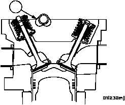
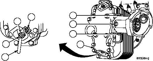
10. Rotate the right camshaft assembly (30) until the two lobes (cams) for the intake and exhaust valves for No. 6R
cylinder are pointed towards the crankshaft. Remove any covers from fuel injector nozzle opening.
Figure 10
30
NOTE
Valve rocker arm covers for cylinder Nos. 1L through 5L
or 1R through 5R for R.B. are not installed until engine is
timed.
11. Install valve rocker arm cover (39) on cylinder No. 6L for L.B. or 6R for R.B. Refer to WP 0026 00.
12. Tighten two screws (11) and screw (52).
13. Using thickness gauge blade (53), set intake valve clearance to 0.010 inch (2.54 mm) by turning the adjusting
screw (54) clockwise to decrease the clearance or counterclockwise to increase the clearance.
14. Check position of valve adjusting screw pad (55) to make sure seat is flat on valve stem.
15. Torque adjusting screw nut (56) to 200--225 lb--in (23--25 NSm).
Figure 8
54
55
56
11
52
11
39
53
|
|