|
|
|
|

|
TM 9--2815--247--34
0082 00--15
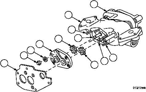
OIL PUMP ASSEMBLY REPAIR -- CONTINUED
0082 00
Assembly -- Continued
11. Install plate (13) onto cover assembly (28).
12. Install impeller (31) on shaft (42) in housing assembly (29) with splines outward.
13. Install impeller (30) on shouldered shaft (40) in housing assembly (29).
14. Install cover assembly (28) onto housing assembly (29).
15. Apply lubricant to five studs (93 and 94).
16. Secure cover assembly (28) to housing assembly (29) using three new self--locking nuts (26) and three flat wash-
ers (27). Torque self--locking nuts to 125--150 lb--in (14--17 NSm).
Figure 19
13
26
27
28
30
31
29
23
42
40
93
94
|
|
|
|
|
Privacy Statement -
Copyright Information. -
Contact Us