TM 9--2815--247--34
0088 00--17
AUTOMATIC FUEL INJECTION ADVANCE CONTROL ASSEMBLY AND
ASSOCIATED PARTS REPAIR -- CONTINUED
0088 00
Assembly -- Continued
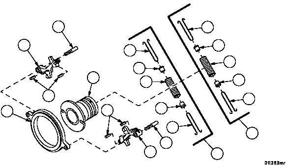
16. Assemble two timing advance retainers (29) and two seats (30) onto compression springs (28) to make two spring
assemblies (72).
NOTE
Three different seat sizes are available and can be
installed in any combination to achieve required load.
17. Check the load on each spring assembly (72) at 2.585 to 2.590 inches (65.6590--65.7860 mm) of stretch using a
spring tester. If the load is not within 3.5 to 4.5 lbs (1.589--2.043 kg) try other seat (30) combinations until required
load is achieved.
18. Install four new spring pins (31) into two flyweight assemblies (17).
19. Install two spring assemblies (72) onto two flyweight assemblies (17).
NOTE
Compression springs and seats are attached to fly-
weights with roll pins driven through timing advance re-
tainer loops.
20. Install two flyweight assemblies (17), with spring assemblies (72) installed, onto adjusting ring (16) with two
threaded pins (24).
21. Spread flyweight assemblies (17) against compression springs (28) and install fluid regulating valve (26) in adjust-
ing ring (16) so slots in fluid regulating valve are aligned with flyweight pins.
24
24
16
26
17
17
28
29
29
30
30
30
30
29
28
29
31
31
72
72
Figure 33
|
|