|
|
|
|

|
TM 9--2815--247--34
0014 00--2
INTAKE AND EXHAUST VALVE CLEARANCE ADJUSTMENT -- CONTINUED
0014 00
Adjust -- Continued
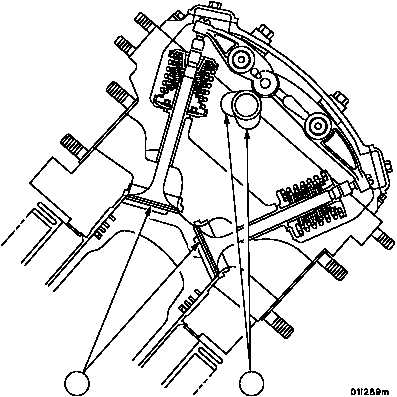
2. Turn flywheel until valves (3) are closed and camshaft lobes (4) are in the position shown.
Figure 10
3
4
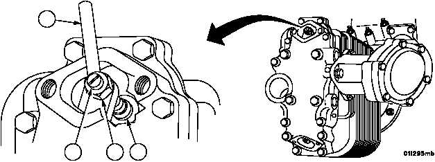
3. Loosen exhaust valve adjusting screw lock nut (5) and turn valve adjusting screw (6) until clearance between
screw pad (7) and valve stem is 0.025 inch using thickness gauge blade (8).
4. Torque lock nut (5) to 200--225 lb--in (22.6--25.4 NSm) after correct adjustment is made. Make certain setting has
not changed after tightening lock nut (5).
Figure 9
8
6
5
7
|
|
|
|
|
Privacy Statement -
Copyright Information. -
Contact Us