ARMY TM 9-2815-252-24
AIR FORCE TO 38G1-92-2
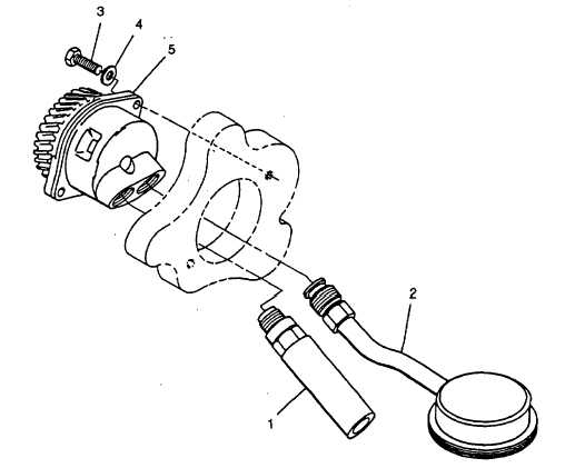
d. From inside crankcase, unscrew oil pressure relief valve (1, FIGURE 3-17) from oil pump (5).
e. Unscrew strainer (2) coupling nut from oil pump (5).
f. Remove two capscrews (3) and washers (4) securing oil pump (5); remove oil pump.
3-21.2. Inspect and Test.
a. Inspect pump for freedom of movement by turning gear.
b. Check oil pressure relief valve setting using hydraulic test stand. Valve should relieve at 47 to 59 psi (324 to
407 kPa).
c. Inspect strainer for blockage and clean as necessary.
d. Inspect all parts for wear or damage and replace defective components.
FIGURE 3-17. Strainer and Oil Pump
3-21.3. Installation.
a. Position oil pump (5, FIGURE 3-17) in crankcase with cutout section of pump behind gear facing top of
crankcase.
b. Secure oil pump (5) with two capscrews (3) and washers (4). Tighten capscrews to 78 in-lbs (8.8 Nm).
c. Install oil strainer (2) in right pump port with strainer gauze parallel with sump base. Tighten retaining nut.
d. Install relief valve (1) in left pump port and tighten retaining nut.
e. Install crankcase door, refer to paragraph 3-20.2.4.
f. Install camshaft, refer to paragraph 3-29.3.
3-39
|
|