ARMY TM 9-2815-252-24
AIR FORCE TO 38G1-92-2
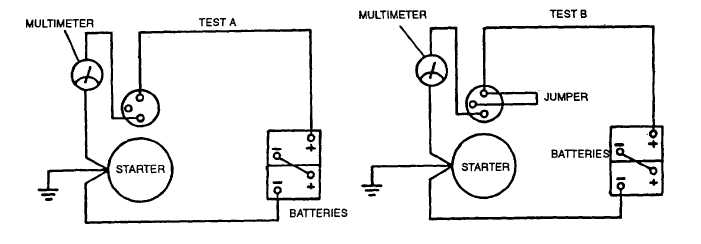
b. Set multimeter for volts DC and connect as shown in FIGURE 3-23, Test A. If voltage is indicated solenoid is
defective.
c. Momentarily connect a jumper as shown in FIGURE 3-23, Test B. Multimeter should indicate battery voltage
and starter should crank the engine. If multimeter does not read battery voltage, the solenoid is defective. If
multimeter indicates battery voltage, but starter does not operate, starter is defective.
FIGURE 3-23. Starter Solenoid Test Circuit
3-24.3.2. Testing Starter Components.
a. Test armature for grounds.
(1) Set multimeter for ohms and touch armature shaft and each commutator bar with multimeter leads.
(2) If multimeter indicates a low reading (approximately zero ohms), armature is grounded and requires
replacing.
b. Test armature for open circuits.
(1) Check for continuity between commutator segments with multimeter.
(2) If an open circuit is indicated, armature must be replaced.
c. Test field coil.
(1) Check for continuity between brushes with a multimeter.
(2) If there is no continuity indicated, field coil is open and field coil frame must be replaced.
(3) Check for continuity between field coil frame and brushes.
(4) If continuity is indicated, field coil is grounded and field coil frame must be replaced.
d. Test solenoid.
(1) Check for continuity between solenoid terminals M and B with a multimeter, refer to FIGURE 3-24.
(2) No continuity should be indicated when solenoid plunger is in normal (out) position.
(3) Push solenoid plunger in and observe multimeter. Multimeter should indicate continuity. If no continuity
is indicated, solenoid must be replaced.
3-48
|
|